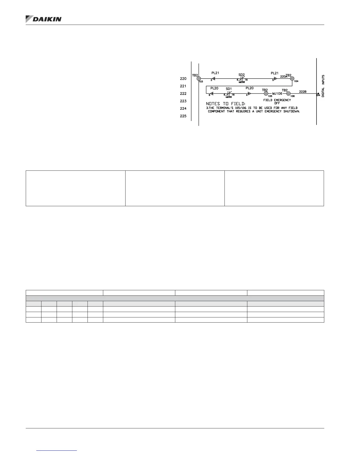
Emergency Shutdown
The terminals 105 & 106 on TB2 can be used for any eld
supplied component that requires a unit emergency shutdown.
When these terminals are used, the factory installed jumper
must be removed.
NOTE: Emergency shutdown Faults can be set to
automatically clear once the condition that caused
the alarm is corrected. This can be accomplished by
navigating to Commission Unit/Alarm Conguration/
Emerg Stop and changing the default No value to
Yes.
Figure 26: Emergency Shutdown Wiring Diagram
OA Damper Flow Station with CO
2
Reset Setup
• At the Microtech controller enter password 6363.
• Scroll down to “Unit Conguration” and click on it.
• Scroll down to “OA Flow Stn” and select “6” for “FS/Rst”
9 OA Flow Station
0 = NONE
1 = DF_015–030 (800)
2 = DF_036–042 (802)
3 = DF_045–075 (047)
4 = DF_080–135 (077)
5 = Generic Flow Station
6 = DGeneric Flow Station w/ CO
2
7 = Ebtron MB
• Scroll up to “Apply Changes” and select “yes” which will
cause the controller to restart.
• Enter password 6363 then scroll down to “Commission
unit” and click on it.
• Scroll down to “Min OA setup” menu and click on it.
• Scroll down to Min OA reset and select “IAQ VDC” or
“IAQ mA” depending on the type of sensor installed.
• Scroll up to “Apply Changes” and select “yes” which will
cause the controller to restart.
CO
2
Sensor wiring
AI 3 Outdoor Temperature 10K Thermistor (STD) All
Universal Inputs/Outputs
# DI AI DO AO Point Comments Cong. Code Condition
X 1 X CO
2
/Min OA/OA CFM 0–10VDC or 4–20 mA 8 = 1, 2, 3, 5, 6, 7, 8 or 9
X 2 X Low Pressure 1 and 2
1
1K & 2K Ohm Input 3 = 1 & 4 > 1 & 4 < H
X 2 X Chilled Wtr 2–10 VDC 3 = 2 or 3 = 3
On all style units (MPS/DPS/RTU/SCU) the CO
2
sensor
needs to be wired to terminals X1 and M at the Microtech III
Controller. Terminal M is the common for all analog inputs.
Make sure the eld wiring polarity is correct to read a valid
PPM value. See Table 4 on page 14
NOTE: The CO
2
sensor (and all eld installed devices)
must be powered from the same transformer as the
controller to prevent damage to the controller.
fIeld wIrIng
www.DaikinApplied.com 29 IM 919-3 • MICROTECH III CONTROLLER