IM 738-2 7
Introduction: Refrigeration Piping
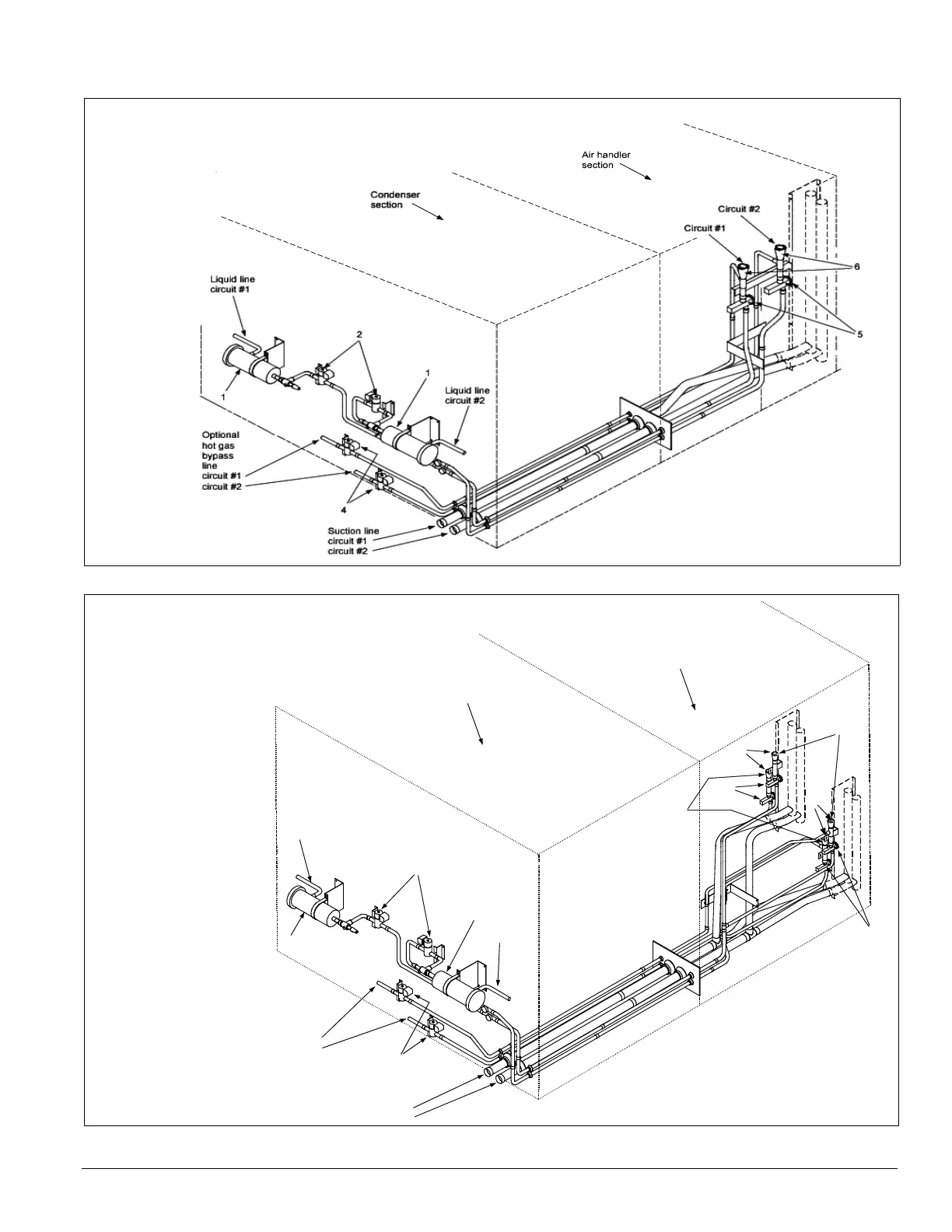
Figure 8. Air handler piping (flat DX)
Figure 9. Air handler piping (staggered DX)
Legend
1 - Filter-drier
2 - Liquid line solenoid valve
3 - Sightglass
4 - Hot gas bypass
and solenoid valve (optional)
5 - Thermostatic
expansion valve
6 - Distributor
Liquid line
circuit #1
2
1
Liquid line
circuit #2
1
Suction line
circuit #1
ir
it
2
Optional
hot gas
bypass
line
circuit #1
circuit #2
4
Condenser
section
Circuit #1
5
5
6
Circuit #2
Air handler
section
6
Legend
1 - Filter-drier
2 - Liquid line solenoid valve
3 - Sightglass
4 - Hot gas bypass and solenoid valve (optional)
5 - Thermostatic expansion valve
6 - Distributor
 Loading...


