IM 893-10 • ROOFPAK SINGLEZONE UNITS 26 www.DaikinApplied.com
MeChanICal InsTallaTIon
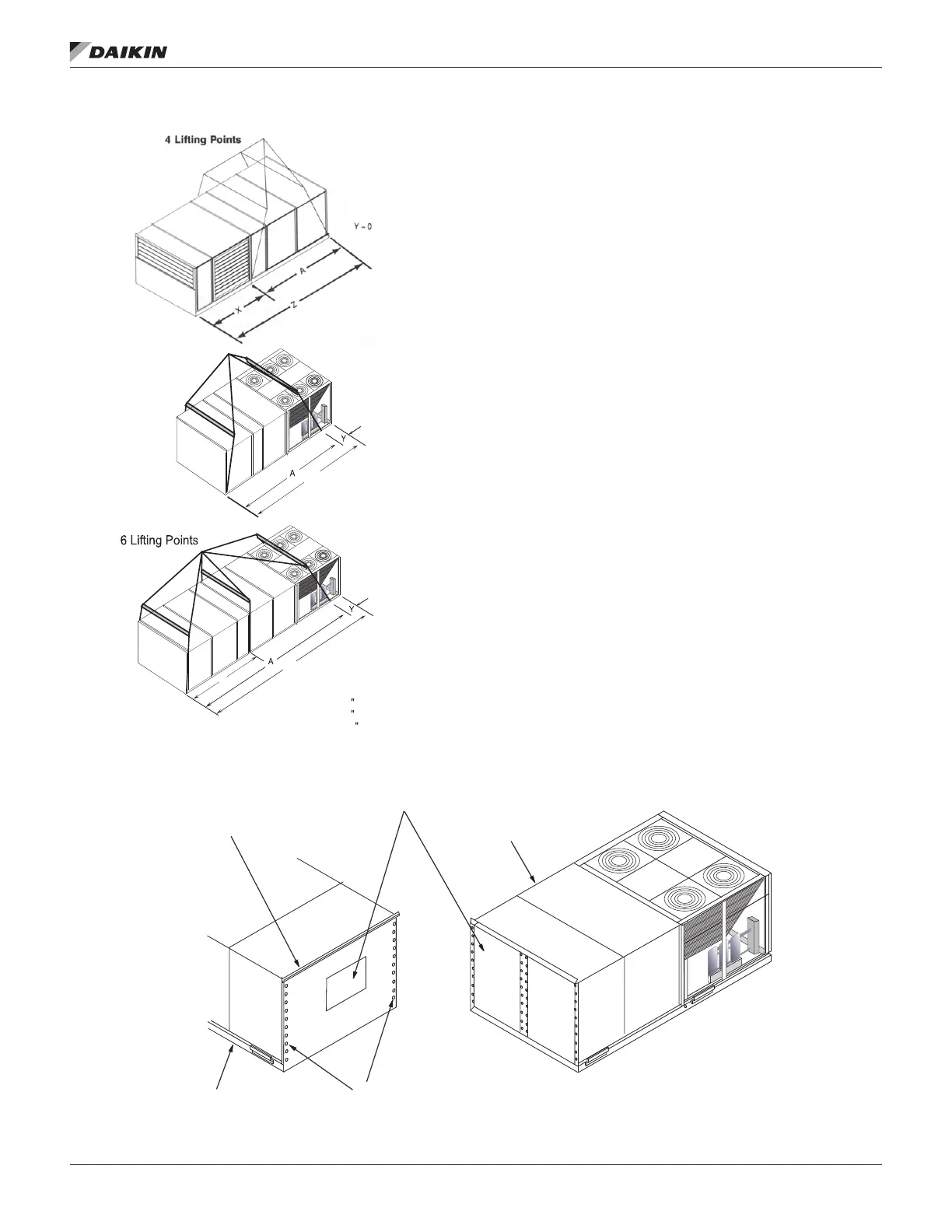
Figure 30: RPS Factory Split at Supply Fan Section
Reassembly of Split Units
Although RoofPak units typically ship from the factory as
complete units, they may be split at the factory in one of two
possible congurations; see (1) “RPS Factory Split at Fan”,
Figure 31 and (2) “RFS/RCS Permanent Split Systems” on
page 29.
RPS Factory Split at Fan
The RPS unit is factory split at the fan section and ships as two
pieces, split at the supply fan bulkhead, to recouple together on
the roof. Like the RPS/RDT unit factory split at the condenser,
this conguration is ordered if shipping length or weight
limitation prevents a packaged RPS/RDT from being ordered.
Splitting at the fan has the advantage of leaving all factory
refrigerant piping intact so eld evacuation and charging is not
required. Detailed instructions are on page 29 to page 28.
A single nameplate is attached to the air handler section and
power is fed to both sections through the main control box, as
in a non-split RPS/RDT unit.
Field reassembly of an RPS/RDT unit that has shipped split
at the fan takes place in three phases: (1) setting the sections
(2) mechanically recoupling the cabinet, and (3) reconnecting
power and control wiring.
Phase I. Set sections (Figure 30)
1. Remove top cap and save for Step 3.
2. Remove screws on fan panel, leaving retainer clips in
place to secure bulkhead. Save screws for Phase II,
Step 5.
3. Remove plywood and retaining angles from unit and
discard.
4. Carefully lower both sections of unit (fan end and
discharge end) into place, making sure the roof curb
engages the recesses in the unit base.
Figure 31: Set Sections - Steps 1-4, RPS Factory Split at Supply Fan
Z
Z
B
045D–068D:BMin. = 72 (1829 mm)
070D–105D:BMin. = 96 (2438 mm)
110D–140D:BMin. = 120 (3048 mm)
Remove top cap and
save for reassembly.
Remove plywood and retaining
angles from unit and discard.
Discharge end of unit
Fan end of unit
Remove screws on fan panel,
leaving retainer clips in place.
Save screws for reassembly.

 Loading...


