Outdoor Unit Si18-797
10 Removal Procedure
4
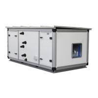
Disconnect the
connectors one by one.
[X2A] Solenoid valve (Hot gas)
[X3A] Solenoid valve
(Receiver gas purge)
[X5A] Solenoid valve
(4 way valve)
[X6A] Crankcase heater
[X22A]Transformer
[X23A]Transformer
[X25A]Connector for [X250A]
[X26A]Electronic expansion
valve(Main)
[X28A]Electronic expansion
valve(Sub cool)
[X34A]Discharge pipe
thermistor
[X37A]Heat exchanger
thermistor
[X44] Air thermistor
[X45A]Pressure sensor (Low)
[X46A]Pressure sensor (High)
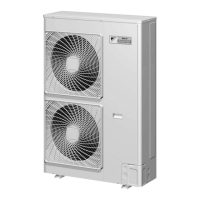
5
Detach the 16 locking
guard spacers.
The cooling only models do
not have the harness for
[X5A].
Preferably use long nose pliers
in removing the locking guard
spacers.
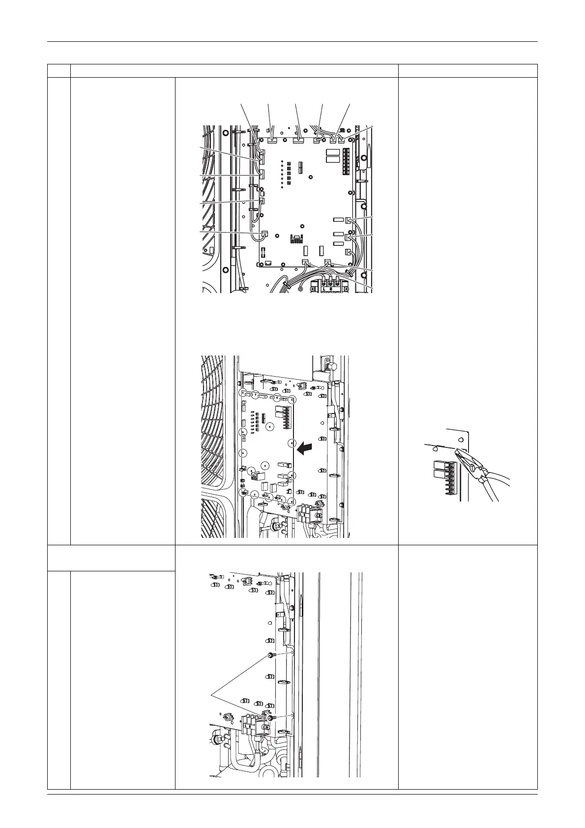
6
Remove the control
PCB.
2. Remove the control PCB
mounting plate.
1
Remove the 2 screws.
Step
Procedure Points
[X25A] [X34A] [X37A] [X44A] [X45A]
[X46A]
[X6A]
[X5A]
[X3A]
[X2A]
[X28A]
[X26A]
[X23A]
[X22A]
(Q0464)
(Q0465)
(Q0466)
Screws
(Q0467)