SiBE041401E Check
Service Diagnosis 94
5.2 Fan Motor Connector Output Check
Check No.02 1. Check the connection of connector.
2. Check the motor power supply voltage output (pins 4 - 7).
3. Check the motor control voltage (pins 4 - 3).
4. Check the rotation command voltage (pins 4 - 2).
5. Check the rotation pulse (pins 4 - 1).
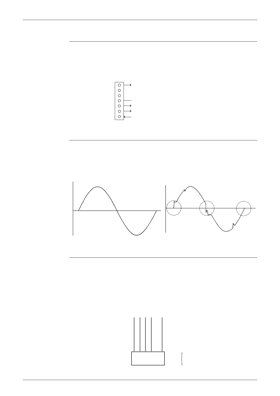
5.3 Power Supply Waveforms Check
Check No.11 Measure the power supply waveform between No. 1 and No. 2 on the terminal board, and check
the waveform disturbance.
Check if the power supply waveform is a sine wave (Fig.1).
Check if there is waveform disturbance near the zero cross (sections circled in Fig.2).
5.4 Electronic Expansion Valve Check
Check No.12 Conduct the followings to check the electronic expansion valve (EV).
1. Check if the EV connector is correctly connected to the PCB.
2. Turn the power off and on again, and check if the EV generates a latching sound.
3. If the EV does not generate a latching sound in the above step 2, disconnect the connector
and check the continuity using a multimeter.
4. Check the continuity between the pins 1 - 6, 2 - 6, 3 - 6, 4 - 6. If there is no continuity between the
pins, the EV coil is faulty.
5. If the continuity is confirmed in step 3, the outdoor unit PCB is faulty.
7
6
5
4
3
2
1
S200
(R19942)
Motor power supply voltage (310 ~ 340 VDC)
Unused
Unused
GND
Motor control voltage (15 VDC)
Rotation command voltage (1~ 6.5 VDC)
Rotation pulse input
Fig.1 Fig.2
(R1736)
(R1444)
Harness 5P
6P Connector
(5)
CheckS20
1 - 6
2 - 6
3 - 6
4 - 6
1 2 3 4 5 6
(R16386)