SiBE041401E Check
Service Diagnosis 98
50 class
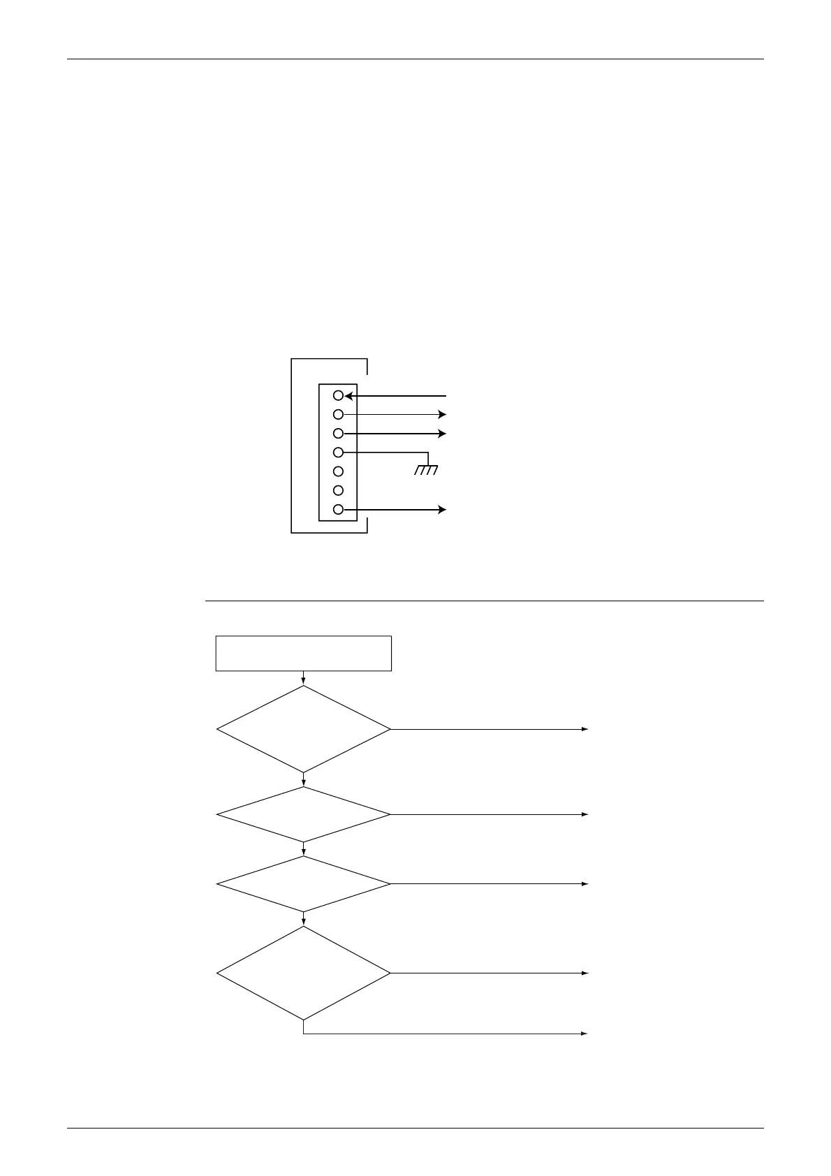
Make sure that the voltage of 320 ± 30 V is applied.
1. Set operation off and power off. Disconnect the connector S70.
2. Check that the voltage between the pins 4 - 7 is 320 VDC.
3. Check that the control voltage between the pins 3 - 4 is 15 VDC.
4. Check that the rotation command voltage between the pins 2 - 4 is 0 ~ 6.5 VDC.
5. Keep operation off and power off. Connect the connector S70.
6. Check whether 4 rotation pulses (0 ~ 15 VDC) are input at the pins 1 - 4 when the fan motor
is rotated 1 turn by hand.
When the fuse is melted, check the outdoor fan motor for proper function.
If NG in step 2
→
Defective PCB
→
Replace the outdoor unit PCB.
If NG in step 4
→
Defective Hall IC
→
Replace the outdoor fan motor.
If OK in both steps 2 and 4
→
Replace the outdoor unit PCB.
5.9 Installation Condition Check
Check No.17
1
2
3
4
5
6
7
320 VDC
(R19655)
S70
PCB
Actual rotation pulse input (0 ~ 15 VDC)
Rotation command voltage (0 ~ 6.5 VDC)
Control voltage 15 VDC
Installation condition check
OK
Check the allowable
dimensions of the air
suction and
discharge area.
Is the airflow blocked by
obstacles or winds
blowing in the opposite
direction?
(R19401)
NG
YES
YES
NO
Is the discharged air
short-circuited?
NO
NO
YES
Is the outdoor heat
exchanger very dirty?
Change the installation
location or direction.
Change the installation
location or direction.
Clean the outdoor heat
exchanger.
Check the outdoor
temperature.
(The outdoor
temperature should be
within the operation range.)
Change the installation location
or direction.