SiBE041401E Outdoor Unit
Printed Circuit Board Connector Wiring Diagram 14
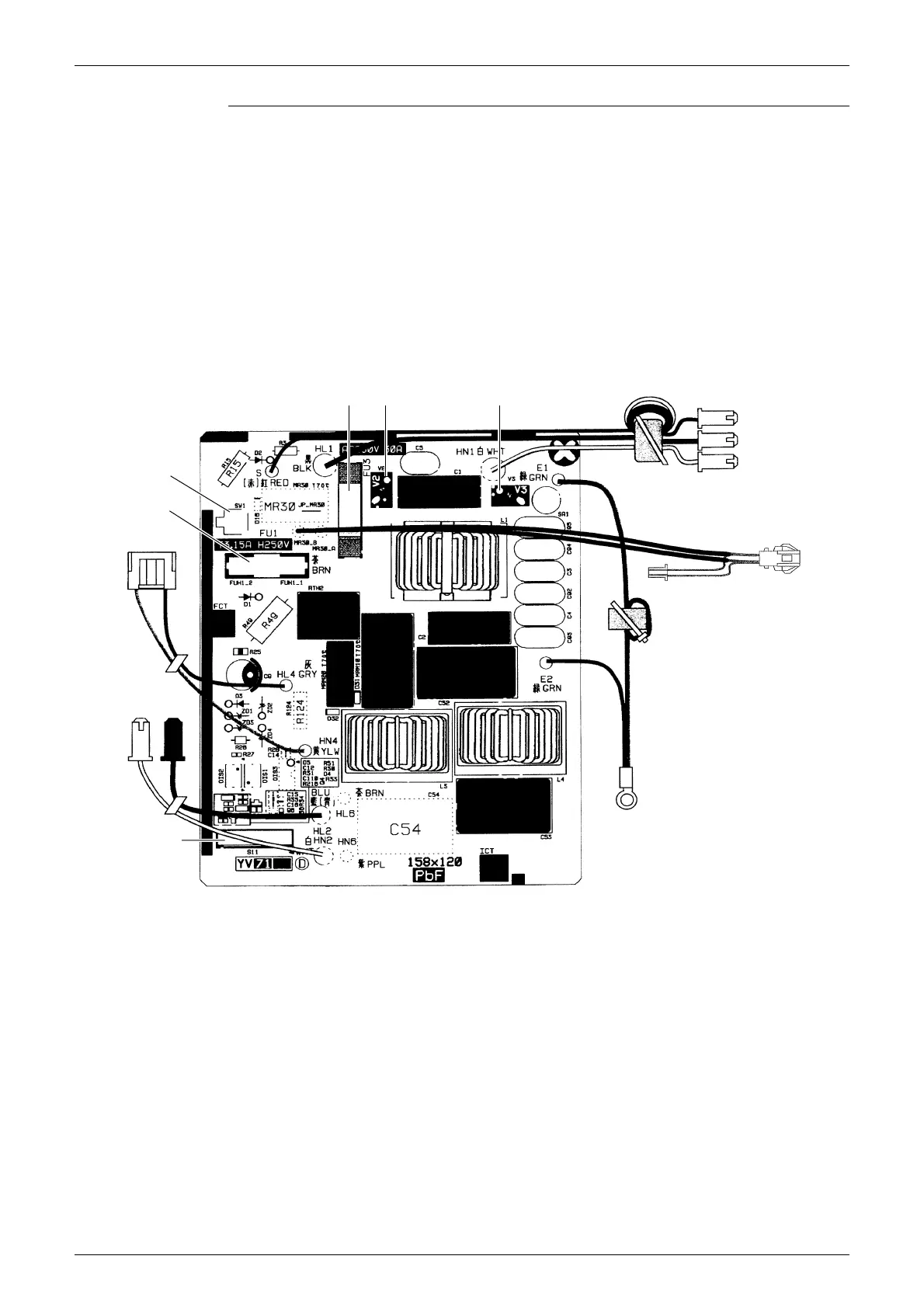
Filter PCB (PCB1)
1) S11 Connector for S10 on main PCB
2) HL1, HN1, S Connector for terminal board
3) E1, E2 Terminal for earth wire
4) HL2, HN2 Connector for HL3, HN3 on main PCB
5) HL4, HN4 Connector for S12 on main PCB
6) FU1 Fuse (3.15 A, 250 V)
7) FU3 Fuse (30 A, 250 V)
8) V2, V3 Varistor
9) SW1 Forced cooling operation ON/OFF button
∗
Refer to page 104 for detail.
to S50
(on main PCB)
S
HL1
HN1
V3V2FU3
SW1
FU1
HN4, HL4
HN2 HL2
S11
E1, E2
3P273862-4