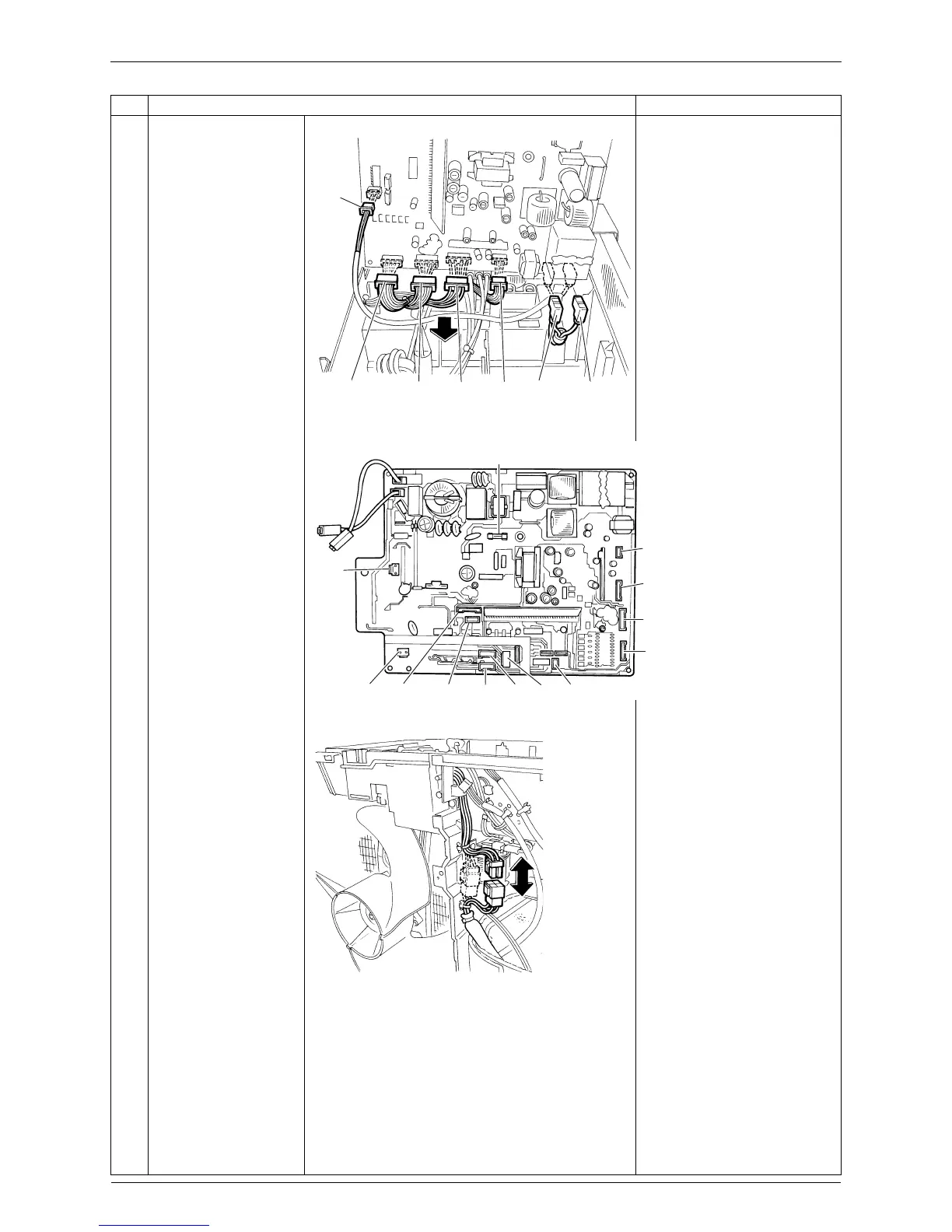
Removal of PCBs / Electrical Box Si00-876
14 Removal Procedure
8
Disconnect the
connectors and remove
the main PCB.
[S10]: terminal board
[S20]: electronic expansion
valve
[S31]: CN14 on SPM
[S32]: CN11 on SPM
[S33]: [S34] on MID
[S40]: overload protector
[S51]: [S52] on service monitor
PCB
[S71]: [S72] on MID
[S80]: four way valve
[S90]: thermistors
[S91]: radiation fin thermistor
[S101]: [S102] on service
monitor PCB
[H1] [H2]: diode bridge
9
Disconnect the relay
connector for the
compressor.
Step Procedure Points
[S31]
[S71] [S33] [S32]
[H2]
(blue)
[H1]
(yellow)
(R2712)
[S91]
[S10]
[S51][S80] [S101] [S20] [S90] [S40] [S91]
[S31]
[S33]
[S32]
[Fu2]
[S71]
(R19136)
(R17065)