IM 770-1 • SKYLINE ROOF CURB 6 www.DaikinApplied.com
insTallaTion
insTallaTion
Curbing Kit Assembly
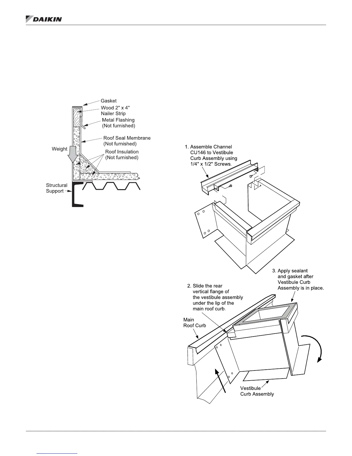
The weight of the unit is concentrated and supported at the
inside wall of the roof curb. The structural system of the
building and the interface with the curb must provide support at
the points of concentrated loads. See Figure 4.
Figure 4: Weight of unit on roof curb
Each curb kit contains a hardware package. The package
contains 3/8–16 × 1ʺ bolts and nuts for assembly of the curb.
Two 1/4–20 × 1/2ʺ screws are included when the unit has a
vestibule. Rolls of gasket are included to cover the top surfaces
of the curb and supports.
The hardware kit includes a layout and assembly drawing of
the curbing with a sketch of the assembly.
Compare the curb layout drawing to the submittal documents
for the air handler to conrm that the details match.
Figure 3 illustrates a typical layout drawing of the roof curb.
Note that each air handler will have a dedicated drawing that
corresponds with the features that are included in the unit.
The curbing parts should be laid out according to the assembly
drawing. The drawing shows dimensions of the parts and
locations of intermediate cross members. The curb parts have
labels attached that correspond with the locations of the parts.
Parts that are identical have the same part numbers. End parts
have number CU122 and center supports have number CU140.
The side supports are shown with sequential numbers CU137,
CU 237 and so on for parts on one side of the drawing.
Likewise, parts on the other side have sequential numbers CU
132, CU 232 in progression. The curb parts for the vestibule
are marked with labels CU 152, CU 156 and CU162.
The dimensions for the locations of all parts are shown and
should be checked carefully for proper assembly order.
Assemble the curb with the 3/8 inch diameter bolts and nuts
that are provided. Always check the dimensions of the curb
before nal installation to the roof and building structure. Also
check to be sure the curb is square and level.
Roof curbs with a Vestibule
Assembly
NOTE: The vestibule assembly channel, part number CU146
must be attached to the vestibule curb assembly
before the vestibule assembly is attached to the main
roof curb. Use two 1/4 × 1/2 screws to attach the
channel.
The vestibule assembly is then attached to the main roof curb
by sliding the rear vertical ange of the vestibule curb under
the lip of the main roof curb. Apply sealant and gasket material
after the vestibule curb is in place. See Figure 5.
Figure 5: Install Vestibule Assembly on Main Roof Curb