SiE12-411 Instruction
System Configuration 119
"
Oudoor Unit
"
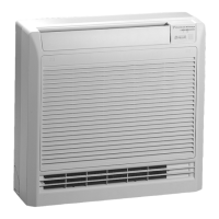
Indoor Unit
"
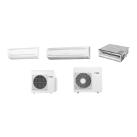
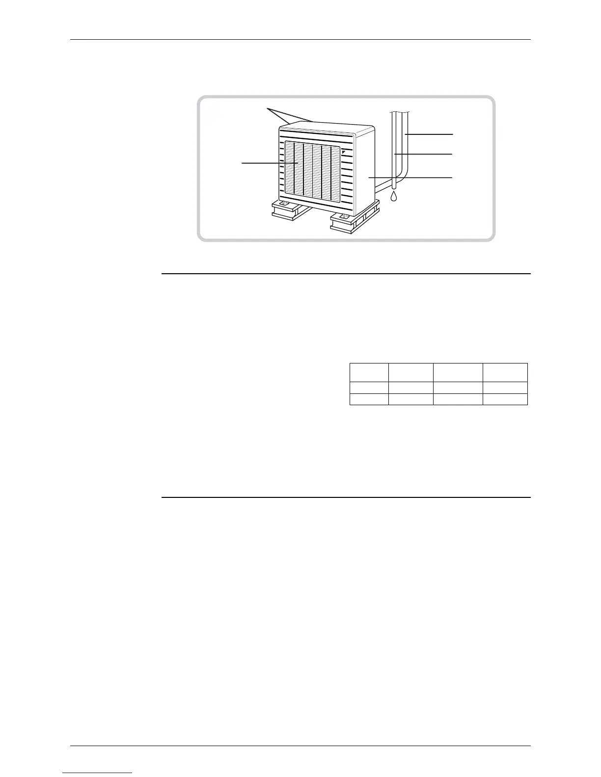
Outdoor Unit
Appearance of the outdoor unit may differ from some models.
1. Air filter
2. Air outlet grille (Field supply)
Appearance of the Air outlet grille and Air
inlet grille may differ with some models.
3. Display, Control panel
4. Suction grille (Option)
• Appearance of the suction grille and Air
inlet grille may differ with some models.
5. Air inlet
6. Room temperature sensor:
• It senses the air temperature around the
unit.
7. Operation lamp (green)
8. TIMER lamp (yellow)
9. HOME LEAVE lamp (red)
• LIghts up when you use HOME LEAVE
operation.
10. Indoor Unit ON/OFF switch:
• Push this switch once to start operation.
Push once again to stop it.
• This switch is useful when the remote
control is missing.
•
The operation mode refers to the following
table.:
11. Air inlet:
(Back and side)
12. Refrigerant piping and inter-unit cable
13. Drain hose
14. Earth terminal:
• It is inside of this cover.
15. Air outlet
12
13
14
15
11
Mode Temperature
setting
Air flow
rate
CDKD COOL 22°C AUTO
CDXD AUTO 25°C AUTO
 Loading...