www.DaikinApplied.com 37 IM 915-13 • VISION - EXTENDED SIZES
Measurement Device
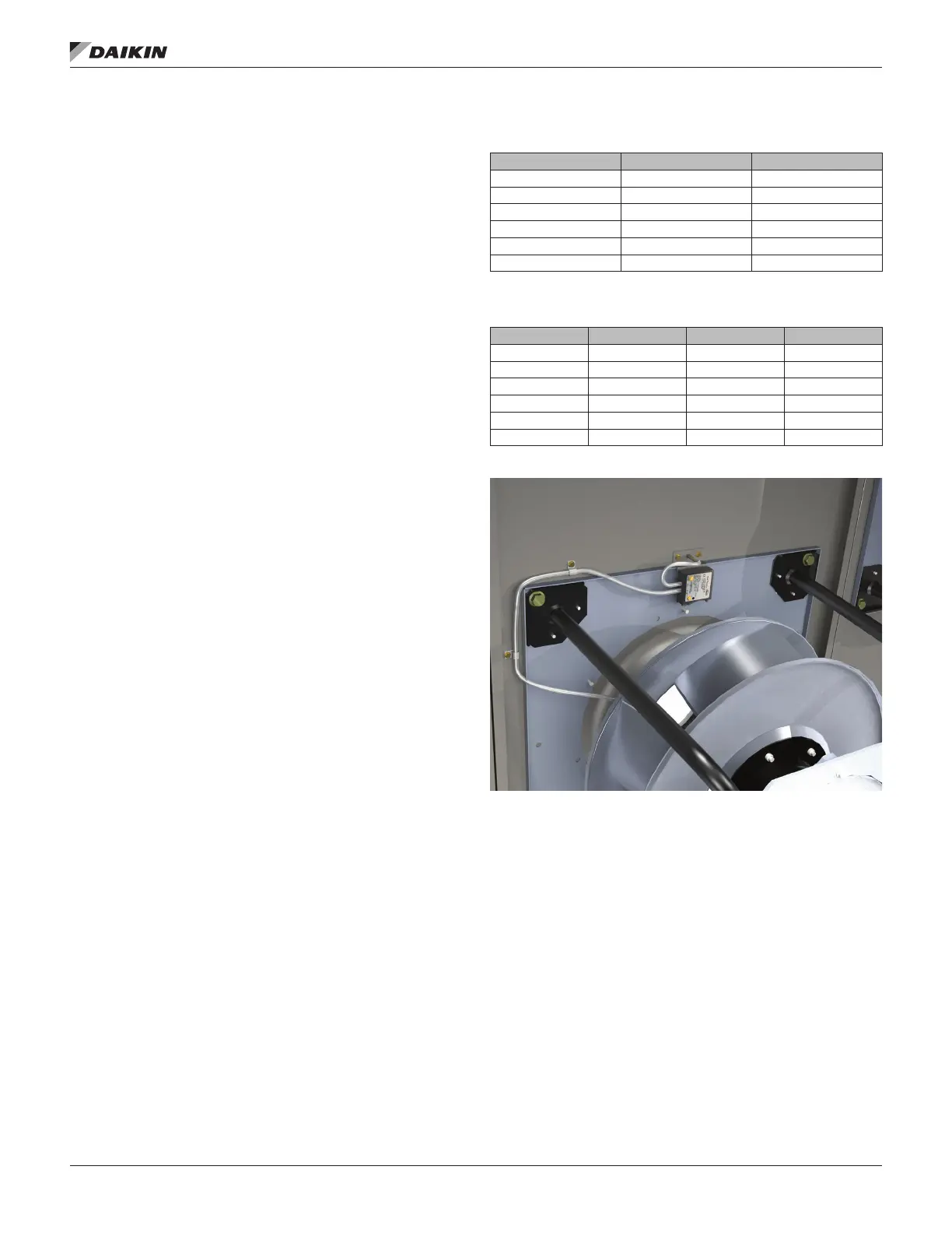
A Piezometer point is an option with EC fans to measure
airow through the fan. The device consists of a piezometer
point mounted in the throat of the funnel and a static pressure
tap mounted near the inlet of the funnel. The pressure drop is
measured from the tap located near the inlet of the funnel to
the piezometer point in the throat. The inlet tap is connected
to the high-pressure side of the transducer and the piezometer
point is connected to the low-pressure side.
A transducer is always factory supplied when the Piezometer
Option is selected with an EC Fan. Figure 65 shows the
installation for EC fans.
See the equations and factors required to calculate ow using
the piezometer point:
Non-Standard Density Method
The following equation is used to measure the ow for
non-standard density:
ACFM = C1 × A × √(ΔP/ρ)
where: A = Inlet funnel throat area (square feet) - from Table 18
ΔP = The dierential in static pressure from the piezometer ring
and the inlet pressure tap (inches w.g.)
ρ = Air density (pounds mass/cubic foot)
C1 = Value from Table 17
Standard Density Method
The equation can be simplied by assuming standard density
and assuming funnel dimensions match the drawing dimensions.
Table 17 shows the factor (F) for each fan size and type. The
equation then becomes the following:
For standard air (ρ = 0.075 lb/ft3):
ACFM = F × √ (ΔP)
where: F = factor from Table 18
ΔP = The dierential in static pressure from the piezometer ring
and the front pressure tap (inches w.g.)
Table 17: ECM Factors for Free and Ducted Inlet —
Non-Standard Density Method
355 774.47 774.47
450 783.31 783.31
560 658.54 658.54
630 666.68 666.68
355D 802.05 802.05
450D 783.31 783.31
Table 18: ECM Factors for Free and Ducted Inlet —
Standard Density Method
Free Inlet F Ducted Inlet F Area A
355 774.47 774.47 0.485
450 783.31 783.31 0.778
560 658.54 658.54 1.341
630 666.68 666.68 1.667
355D 1459.58 1459.58 0.498
450D 2283.43 2283.43 0.798
Figure 65: Piezometer Transducer