IOM 1281-2 • CENTRIFUGAL WATER CHILLERS 36 www.DaikinApplied.com
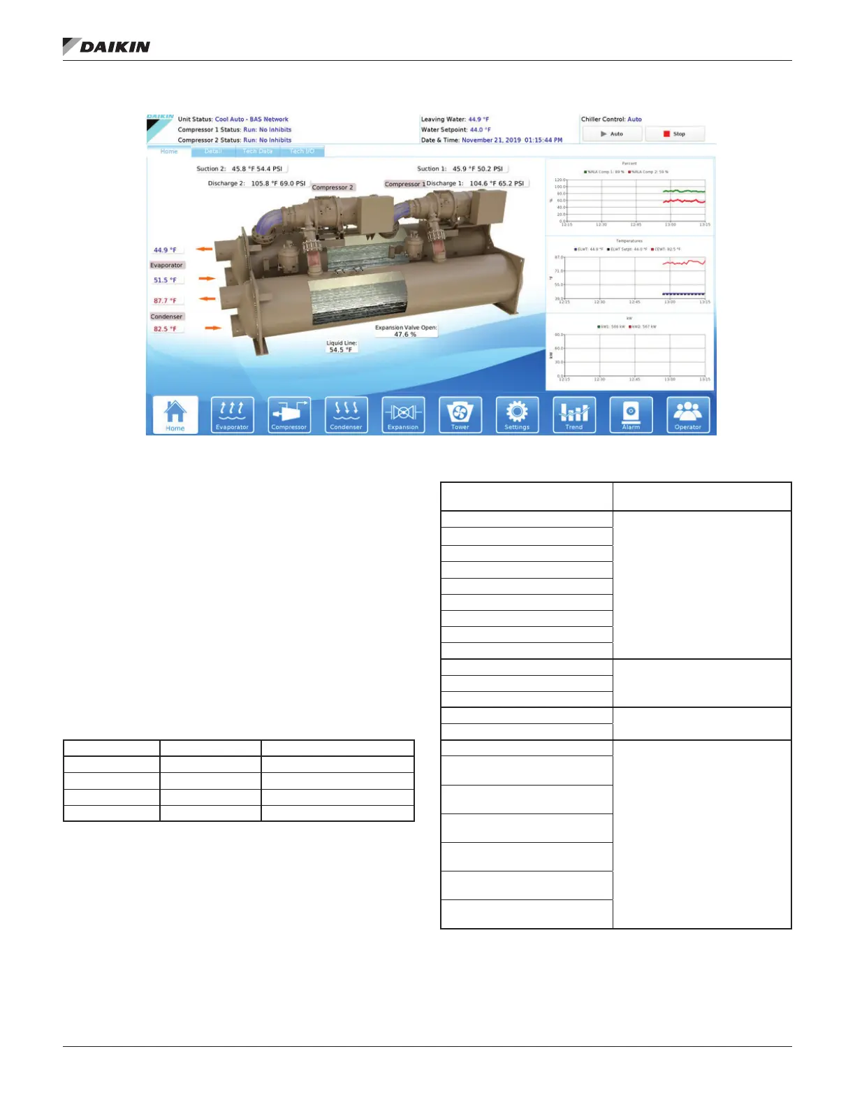
Figure 34: Home View Screen
The Home View Screen (Figure 34) shows the basic operating
condition of the chiller. Note that the chiller displayed on all
screens will be representative of the actual chiller, showing
either one or two compressors depending on the chiller model.
image.
The top banner across all screens
will always show the following:
• Actual leaving water temperature
• Chilled water setpoint
• Date and Time
• Chiller Control Source
• Unit Status - the possible status combinations are shown
in Table 9 and discussed below.
Table 9: Unit Status Possibilities
MAIN MODE STATE SOURCE (for stop)
Cool Manual/Mechanical Switch
Ice Shutdown Digital Remote Switch
Heat Auto Local Unit
BAS Network
• Chiller can only be in one of the three main operating
modes at a time; however, the available mode setpoint
may be a combination of COOL, w/ GLYCOL, ICE, and
HEAT. For example, Cool/Ice w/ Glycol is an available
mode setpoint but the chiller can only be in either COOL
or ICE mode at any given time.
•
compressor units), is Mode followed by State followed by
the Source device or signal. The possible combinations
are shown in Table 10.
Table 10: Compressor Status Possibilities
(in priority sequence)
Notes
OFF Manual Switch
Reason for the
OFF Compressor Alarm
OFF Unit State
OFF Evap Flow/Re-circulate
OFF Low Oil Sump Temp
OFF Start to Start Timer = xxx
OFF Stop to Start Timer = xxx
OFF Staging (Next ON)
OFF Awaiting Load
PRELUBE Vanes Open
Compressor is in START state
- Current state of the Prelube
sequence
PRELUBE Timer=xxx
PRELUBE Condenser Flow
RUN Unload Vanes-Max Amps
Overrides water temperature
command
RUN Hold Vanes-Max Amps
RUN Manual Vanes & Speed
password required. Operated
from compressor controller
RUN Load Vanes-Manual
Speed
RUN Hold Vanes-Manual
Speed
RUN Unload Vanes-Manual
Speed
RUN Load Speed-Manual
Vanes
RUN Hold Speed-Manual
Vanes
RUN Unload Speed-Manual
Vanes