SINGLE SCREW CHILLERS IMM
28 Engineered for Flexibility and Performance
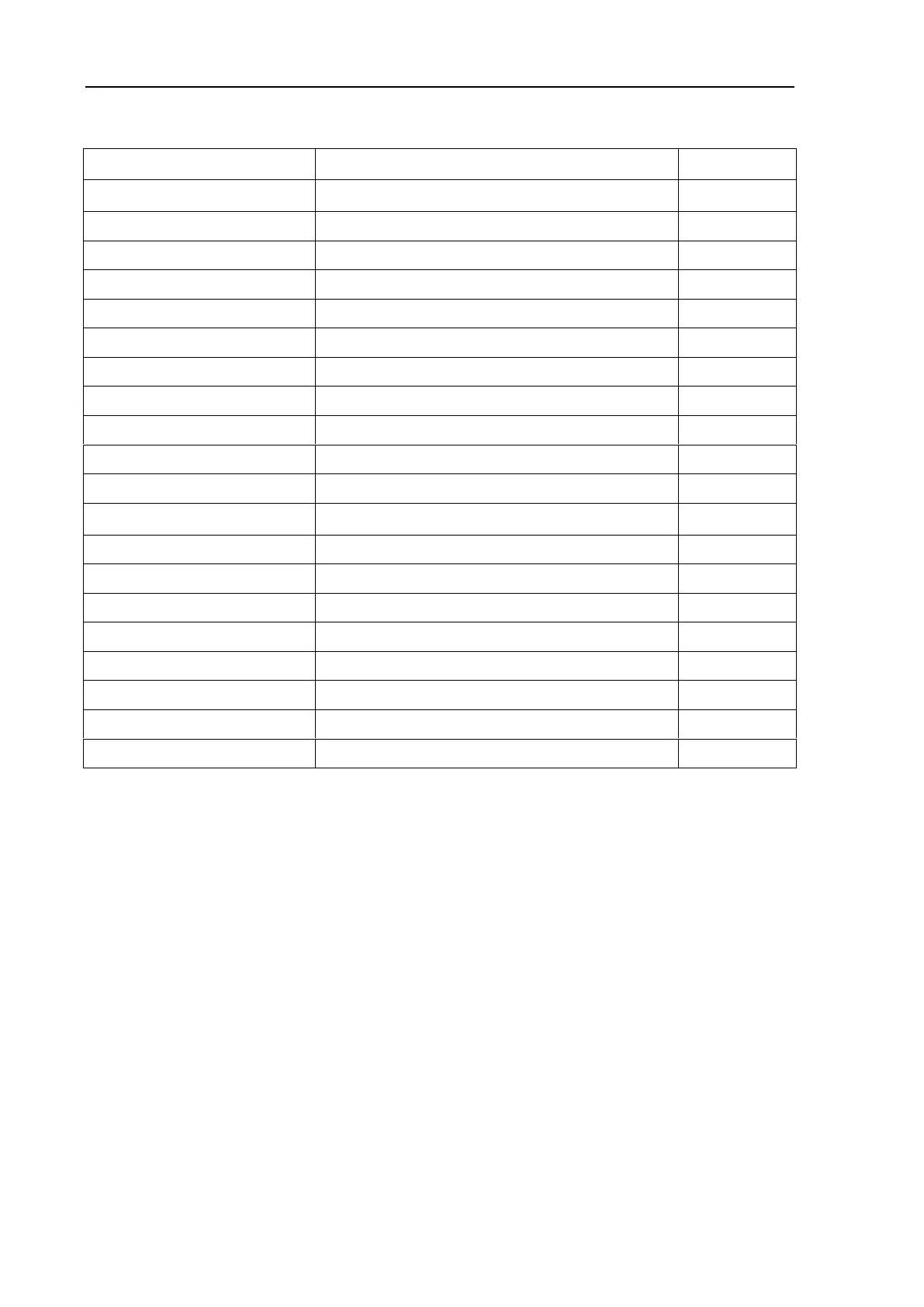
Description of Valve Application
Refrigerant charging valve
Pollution discharging valve
Bottom of evaporator head
Rear of Evap. (near Cond)
Refrigerant discharging valve
Pollution discharging valve
Left of Cond (facing starter)
Bottom of evaporator head
Pollution discharging valve
Suction valve (if available)
Drainage tube ball valve (if available)
Suction-type Oil-spray Pipeline
Stop valve of Suction-type Oil-spray Pipe (if any)
Liquid-spray Pipeline Stop Valve (if any)
Balance Pipe Stop Valve (if any)
Notes: ※ Please refer to the orifice table in container as-built drawing for specific positions of
each stop valve.
※※ The setting of safety valve is of great importance. Please check the stability of the safety
valve carefully. Refer to [4.4 Notes for Relief Valve]
7.6 Panel setting check
Check if setting values are matched the chiller.
Before chiller start-up, bring panel settings into correspondence with customer system.
Enter “System settings” interface to set parameters (password is requested).