SINGLE SCREW CHILLERS IMM
48 Engineered for Flexibility and Performance
Appendix D
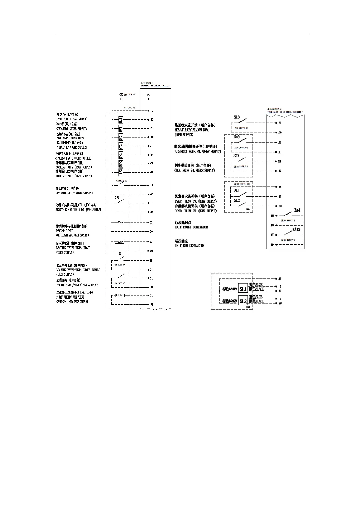
Field Wiring Diagram of Control cable
Note:
1. This drawing has DC wires and 220VAC wires; it is recommended that DC wires
be run separately from 220VAC wires.
2. Only heat Recovery Unit need to connect this signal.
3. If users order the External Fault Output function, users need to supply an alarm
signal, connect the NO contactor of the alarm relay between No. 1 and No. 62
terminals.
4. If users order the Remote Start/ Stop function, connect a switch (user supply)
between No. 21 and No.35 terminals can realize the function.
5. If users order the Leaving Water Temp. Reset function, connect a switch (user
supply) between No. 21 and No.31 terminals can realize leaving water
temperature reset enable function.
6. If users need to control evap. pumps, cond. pumps and cooling fans, connect the
coins of 220VAC relays (user supply) to the corresponding terminals, using the
contactors of those relays to control the pumps and the fans.
7. If users order the Unit Fault Output function, the cabinet supplies a passive
contactor between No. 15 and No.16 terminals. If users order the Unit Run Output