Introduction
3
Remove the Spare Parts Rack
Spare parts are located inside the
display cabinet behind the bottom-
left doors. Refer to Figure 3.
To access modules located behind
spare parts, remove the spare parts
rack.
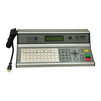
1� Remove the two wing nuts that
secure the spare parts rack to
the display cabinet. Refer to
Figure 4.
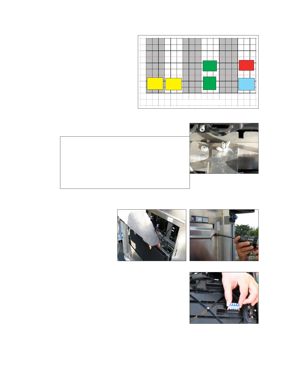
2� Lift the spare parts rack off of
the mounting studs. Refer to
Figure 5. A second set of
mounting studs is located near
the bottom of the display.
Note: After performing service or completing
connections, replace the display door and
ensure it is attached to the safety lanyard
and secured with a screw (#10-24 X0.625 hex
head, Daktronics part number HC-1554) in
the provided location on the top-right side of
each door. Refer to Figure 6. Find replacement
screws in a bag in the spare parts area.
Remove Module From Spare Parts Rack
1� With one hand on the
module face, insert
the
1
/
8
" hex head
wrench into the
bottom access hole.
2� Turn the latch release
approximately
a quarter-turn
counterclockwise.
3� Insert the
1
/
8
" hex head
wrench into the top
access hole.
4� Turn the latch release approximately a quarter-turn
counterclockwise. You should feel the module release
from the display face.
5� Disconnect the SATA cables from the back of the
module.
6� Remove the plug inserted into the power jack. Refer
to Figure 7.
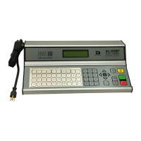
Spare
Parts
Spare
Parts
ISP Box
Power Entrance/
Term Panel
DMP-8065
SmartLink
and
Relays
1
2
3
4
5
6
7
8
9
1
2
3
4
5
6
7
8 9
10
11
12
13
14
15 16
17
18
Rear View: 9x18 (11'x22') Poster
Figure 3: Spare Parts Rack in Display
Figure 4: Wing Nut Securing
Spare Parts Rack
Figure 5: Lift Spare Parts Rack
From Cabinet
Figure 6: Removing Door Screw
Figure 7: Remove Plug From
Power Jack on Spare Module

 Loading...