Accessories
10
3 Accessories
This section describes optional accessories that are available with the HS-200 horn start.
Backstroke Flagpole Bracket
The Backstroke Flagpole Bracket (Figure 13) allows the horn
start to be mounted to the backstroke agpole. When pool
deck space is limited, this eliminates the clutter of a podium
or tripod on the deck and the possibility of the unit being
knocked into the pool. The backstroke agpole is also a good
position for the horn start because sound is distributed evenly
across the lanes.
Attaching the Horn Start to Flagpole
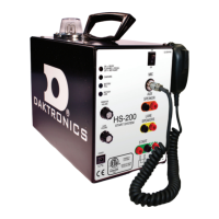
1� Use a #2 Phillips screwdriver to remove top-middle screw
and the two right-rear screws identied in Figure 14.
2� Mount the backstroke agpole bracket as illustrated in Figure 15.
3� Re-install the three screws removed in Step 1.
4� Use both locking straps to securely fasten the unit to the agpole.
Remote Strobe
Mounting Bracket & Strap
A mounting bracket and strap are included with
the remote strobe for mounting to a backstroke
agpole or to a start block. The remote strobe also
has rubber feet for setting on any at surface.
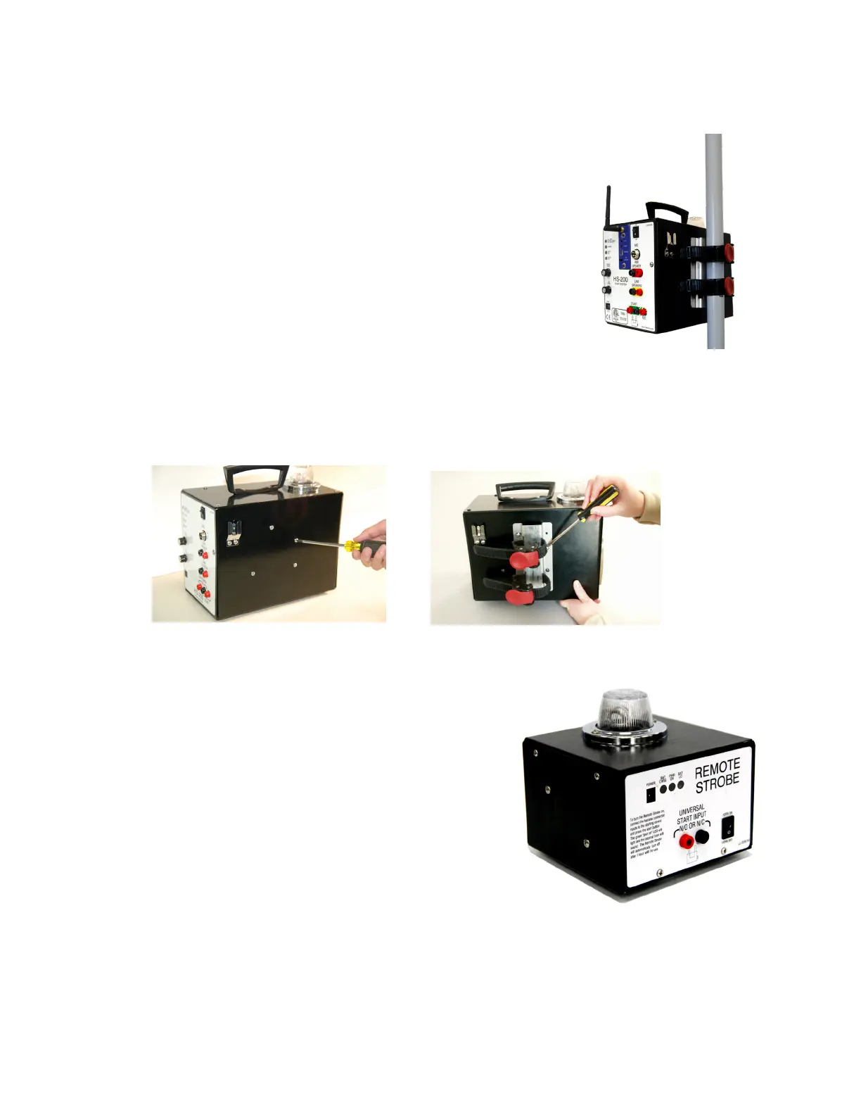
Battery Operation
The HS-200 remote strobe includes an internal
12 VDC battery that provides up to 15 hours of
continuous use. Using the remote strobe on battery
power requires one end of a start extension cable
with the dual banana plug to be plugged into the
UNIVERSAL START INPUT (Figure 16).
The other end of the cable should plug into either the START or N/C jack on the HS-200.
If the HS-200 is also connected to the OmniSport timer, the remote strobe cable will
piggyback onto the timer output cable. Use the START output when using Daktronics or
CTS timers. Use N/C when using Omega timers.
Figure 13: Flagpole Bracket
Figure 14: Remove Screws
Figure 15: Attach Bracket
Figure 16: Remote Strobe