System Setup & Operations
3
2 System Setup & Operations
HS-200 Indicators, Switches, Knobs & Connections
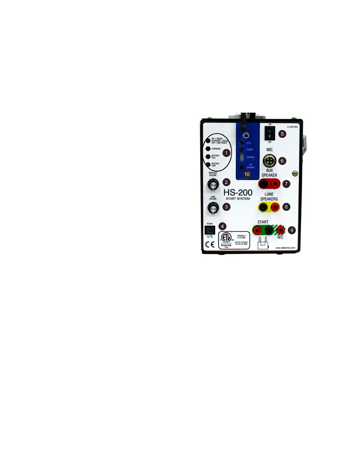
The connection panel of the HS-200 horn start (Figure 3) is where all connection,
adjustments, and status indicators are located.
1� The group of four LEDs stacked vertically on the upper left corner performs two
functions. Their main function is the one for which they are labeled. The LEDs are also
used to indicate the rmware revision during power-up and to also designate when
the unit is in programming mode. Refer to Operations (p�6).
• ON-READY LED indicates when the HS-
200 horn start is ready to start the next
race, in recall mode, or not ready.
• CHARGING LED indicates when the horn
start is connected to main power and
charging the battery.
• BATTERY FULL LED will be on if the power
switch is turned on, and the battery is
completely charged.
• BATTERY LOW LED will be on if the power
switch is turn ON, and the battery is low.
2� The MAIN/AUX VOLUME control knob sets
the volume of the internal speaker built into
the HS-200 horn start plus the volume of
the speaker plugged into the jacks labeled
AUX SPEAKER.
3� The LANE VOLUME control knob sets the
volume of the speakers plugged into the
jacks labeled LANE SPEAKERS.
4� The POWER connection is for a universal 12 VAC power pack.
5� ON/OFF switch is the main power switch. Turn switch to OFF when the device is not
being used.
6� The MIC jack is a standard CB style 4-pin cobra/uniden microphone connector. A
microphone extension can be used if it does not exceed 50’ (15 m).
7� The AUX SPEAKER jacks typically connect to the Auxiliary Speaker cable. If there are
no lane speakers, plug the Aux Speaker cable into the LANE SPEAKER jacks. This will
give separate volume control of the Aux Speaker and the internal speaker on the
horn start in addition to each of them having their own dedicated amplier.
8� The LANE SPEAKERS jacks typically connect to the cable from the Lane Speakers.
9� START and N/C jacks connect to the timing console start input. The black jack is the
GND tab that the start cable plugs into.
The START jack output is a Normally Open switch contact, meaning the switch output
is open and closes momentarily to signal the start of the race. The N/C jack output is
a Normally Closed switch contact, meaning the switch output is closed and opens
momentarily to signal the start of the race.
10� These controls and indicators are for the wireless microphone. Refer to Wireless
Microphone (p�11) for more information on wireless microphone setup.
Figure 3: HS-200 Connection Panel