12 Spyder2 4k User’s Manual
03-032-10195-04 DALSA
2.3 Connectors, Pinouts, and Cables
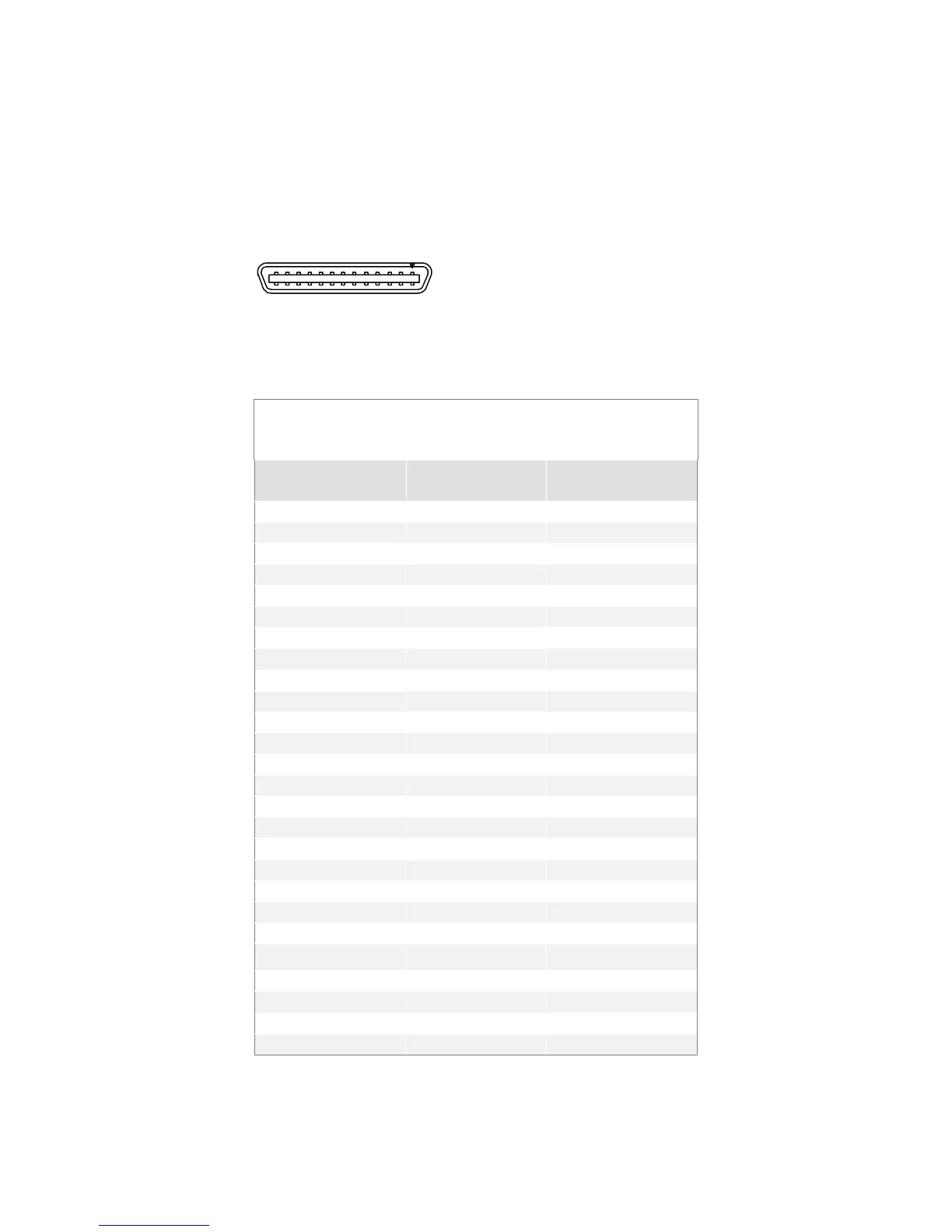
The camera uses a high-density 26 pin MDR26 connector for Camera Link control signals,
data signals, and serial communications, and a 6 pin Hirose connector for power.
Table 3: Camera Link Base Configuration
Base Configuration
One Channel Link Chip + Camera Control +Serial
Communication
Camera Connector
Right Angle
Frame Grabber
Channel Link
Signal
1 1 inner shield
14 14 inner shield
2 25 X0-
15 12 X0+
3 24 X1-
16 11 X1+
4 23 X2-
17 10 X2+
5 22 Xclk-
18 9 Xclk+
6 21 X3-
19 8 X3+
7 20 SerTC+
20 7 SerTC-
8 19 SerTFG-
21 6 SerTFG+
9 18 CC1-
22 5 CC1+
10 17 CC2+
23 4 CC2-
11 16 CC3-
24 3 CC3+
12 15 CC4+
25 2 CC4-
13 13 inner shield
26 26 inner shield
Unused pairs should be terminated in 100 ohms at both ends of the cable.
MDR26 Female
1
14
13
26
Mating Part
: 3M 334-31 series
Cable:
3M 14X 26-SZLB-X XX-0LC
**
 Loading...


