7 Spyder2 4k User’s Manual
03-032-10195-04 DALSA
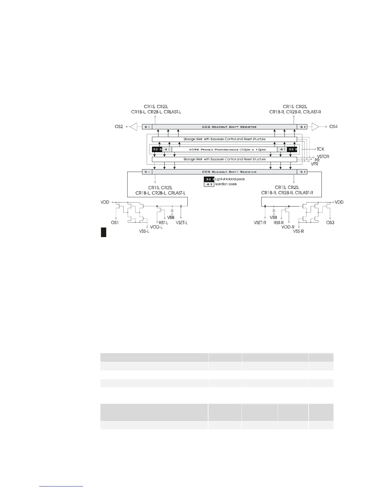
1.2 Image Sensors
The Spyder2 4k cameras use the IT-P1 image sensor, with 10 µm square pixels, 100% fill
factor, and pinned photodiodes.
Figure 1: IT-P1 Image Sensor
Relative position
of package Pin 1
1
1.3 Camera Performance Specifications
The following two tables list the camera’s performance specifications. The first table lists
the operating ranges of the camera, and the second table lists the performance
specifications at minimum, nominal and maximum gain levels at 1 kHz data rate. Note
that as gain levels increase, performance decreases, because your signal to noise
decreases.
Also note that most of the camera’s performance specifications were obtained using a line
rate of only 1 kHz. At low line rates, dark current can become a significant source of noise
and appears in specifications such as FPN and PRNU. If you operate the camera at faster
line rates, such as 9 kHz, the amount of dark current will be reduced by 9x or greater.
Table 1. Spyder2 4k Operating Requirements and Ranges
Operating Requirements Units Typical Notes
Power W 7
Power Supply Current (Vin = +12V) mA 750
Time to power up, typ sec. 15
Time to calibrate (FPN/PRNU) sec. 38
Specification Units Min Max
Notes
Throughput MHz 40 40
Line Rate kHz 10
 Loading...


