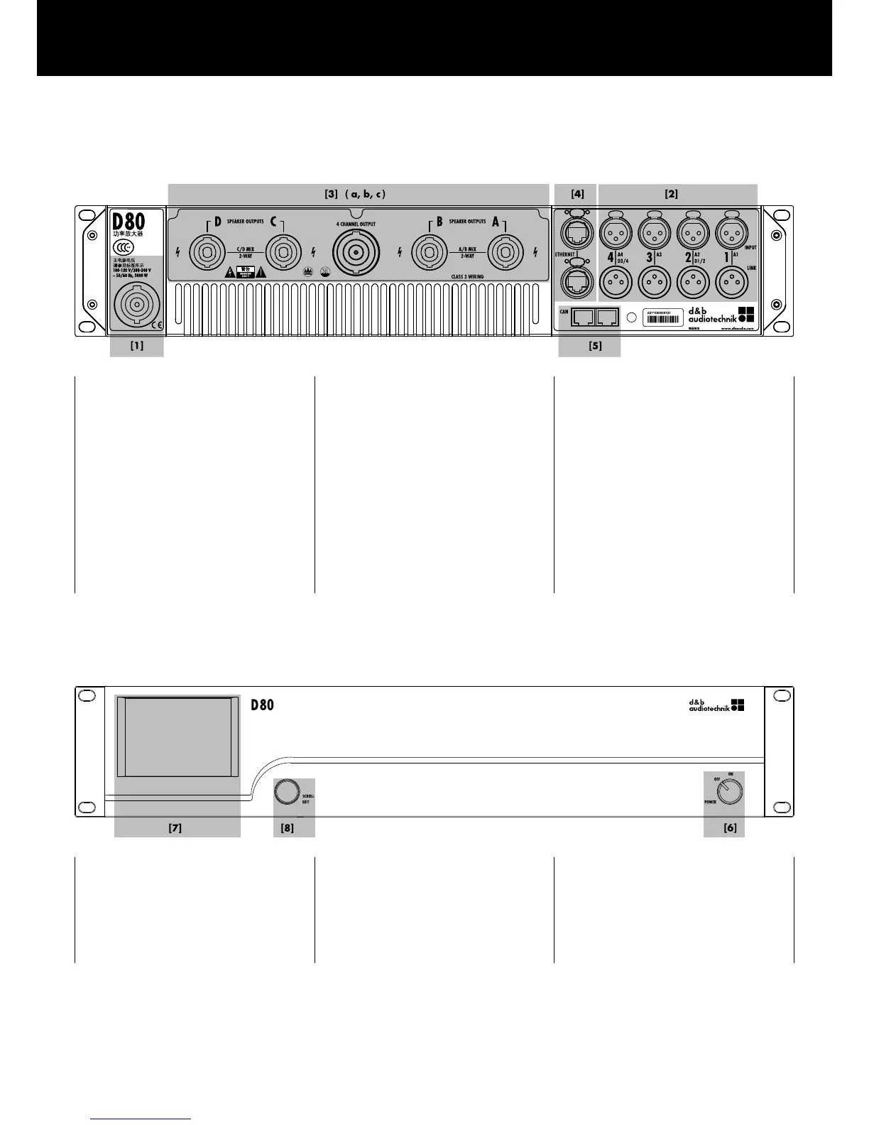
[1] Mains connector socket.
Refer to Þ Chapter 4.3.1. "Mains
connection" on page 14 and
Þ Chapter 12.1.5. "Mains supply
requirements" on page 66.
[3] Output connector panel, dependent
on chosen output option (NL4 or EP5
output connectors).
Refer to Þ Chapter 4.3.3. "Output
connectors" on page 17.
[2]
Audio INPUT (analog/digital) and
LINK connectors.
Refer to Þ Chapter 4.3.2. "Audio
INPUT and LINK connectors"
on page 16.
[4] ETHERNET.
Refer to Þ Chapter 4.3.4.
"ETHERNET (Dual Ethernet port)"
on page 18.
[5] CAN (CAN-Bus).
Refer to Þ Chapter 4.3.5. "CAN
(CAN-Bus)" on page 19.
Controls and indicators - User interface
[7] 3.5" TFT color touch screen.
[8] Rotary encoder SCROLL/EDIT.
Refer to Þ Chapter 4.4. "Controls
and indicators" on page 20 and
Þ Chapter 5. "User interface"
on page 23.
[6] Mains power switch.
Refer to Þ Chapter 4.4. "Controls
and indicators" on page 20,
following Þ Chapter 4.4.1. "Mains
power switch" on page 20.
4. Startup
d&b D80 Manual 1.8 en 11