12.3. Cooling fans
Three temperature and level controlled fans are incorporated for
cooling the internal components, which allows greater cooling
during louder program material. The fan speed is consequently
reduced during quieter passages preventing background noise
interference. If the unit heats up a «Temp. Warning» is issued and
the fans will give full cooling power permanently.
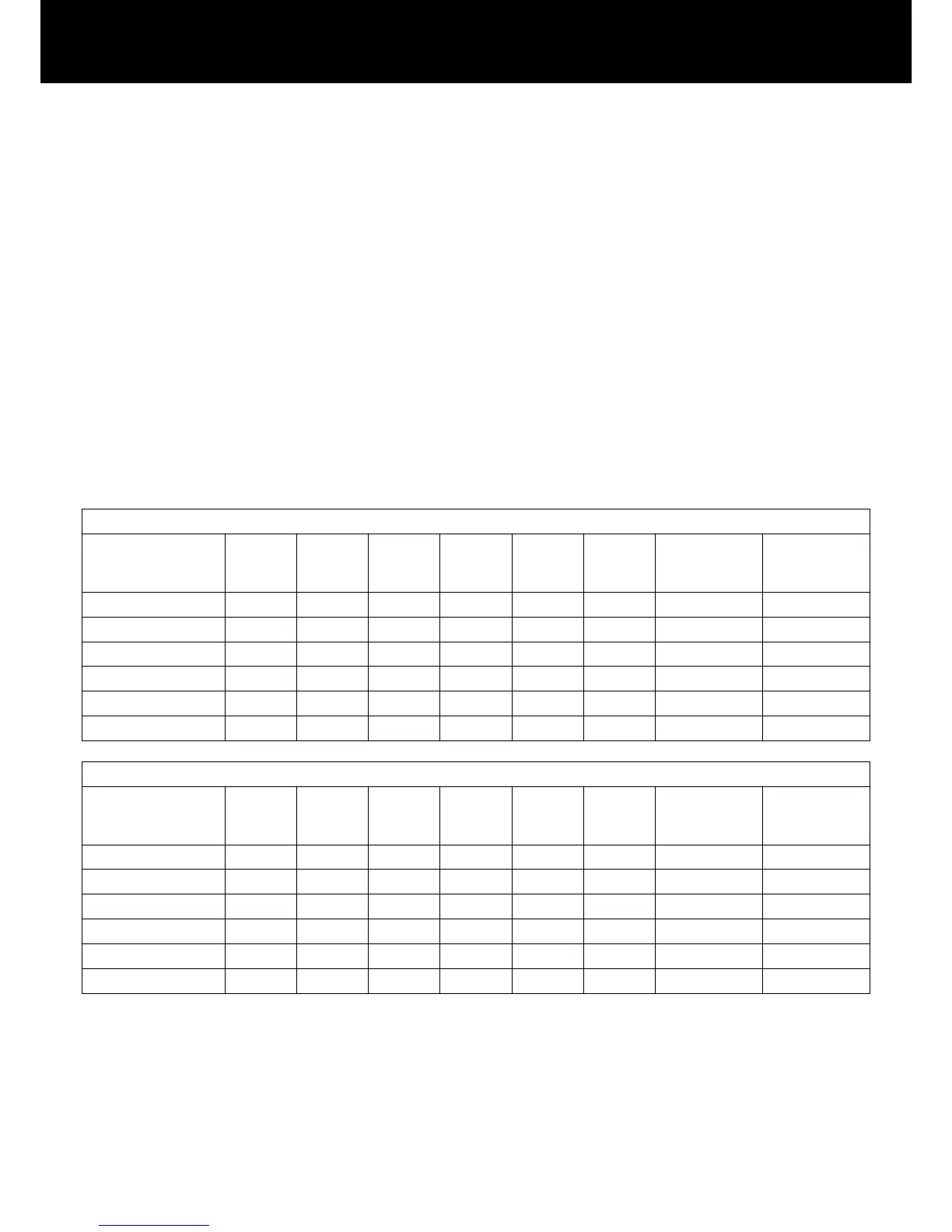
12.4. Current/power draw and thermal dissipation
Measurement references
Signal CF 12 dB: Represents 1/8th of the nominal power.
Signal CF 9 dB: Represents 1/4th of the nominal power; power
is limited to the nominal line current.
Continuous (cont.): Unlimited time. Thermal conditions may
affect power figures.
Maximum (max.): Values are measured 1 sec. after signal was
applied.
230 V AC / 50 Hz / 0.5 Ω Source impedance
Mode/Level Load
Line
current
A
RMS
Power
factor
Input
power
W
Output
power
(sum.) W
Power
loss
W
Thermal
dissipation
BTU/hr
Thermal
dissipation
kCal/hr
POWER switch off – 0.14 0.08 2 0 2 7 2
Standby – 0.18 0.26 10 0 10 34 9
On, idling – 0.85 0.83 162 0 162 553 139
Signal CF 12 dB cont. 4 Ω/Ch. 12.50 0.98 2780 2150 630 2150 542
Signal CF 9 dB cont. 4 Ω/Ch. 18.00 0.98 4140 3136 1004 3426 863
Signal CF 9 dB max. 4 Ω/Ch. 24.00 0.98 5500 4000 1500 – –
208 V AC / 60 Hz / 0.5 Ω Source impedance
Mode/Level Load
Line
current
A
RMS
Power
factor
Input
power
W
Output
power
(sum.) W
Power
loss
W
Thermal
dissipation
BTU/hr
Thermal
dissipation
kCal/hr
POWER switch off – 0.13 0.08 2 0 2 7 2
Standby — 0.18 0.25 10 0 10 34 9
On, idling – 0.93 0.82 160 0 160 546 138
Signal CF 12 dB cont. 4 Ω/Ch. 13.80 0.98 2822 2150 672 2293 578
Signal CF 9 dB cont. 4 Ω/Ch. 18.00 0.98 3635 2800 835 2849 718
Signal CF 9 dB max. 4 Ω/Ch. 27.00 0.98 5600 4000 1600 – –
d&b D80 Manual 1.8 en68