Do you have a question about the Danfoss 088U0210 and is the answer not in the manual?
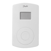
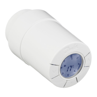
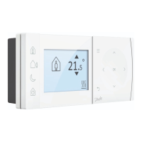
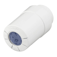
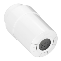
Details the front features: turning knob and push button, and red LED.
Explains the different states of the LED indicator: ON, OFF, Flashes, Flickers.
Identifies components on the back: back plate, knob release, mounting holes, battery placement, screws.
Describes the process of releasing the turning knob from the thermostat.
Explains setting temperature limits: minimum (blue, 10°C) and maximum (red, 30°C).
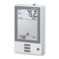
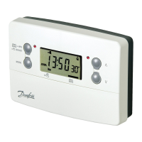
Steps to put the Master Controller into installation mode using buttons and LED indicators.
Procedure to activate installation mode on the Room Thermostat via its push button and LED.
Guide to selecting the desired output channel on the Master Controller using buttons and LEDs.
Interpreting LED feedback to determine if Room Thermostat installation was satisfactory or not.
How to start the transmission test on the Room Thermostat using its push button and LED.
Indicates a successful transmission link when the LED goes OFF after the test.
Shows an unsuccessful transmission link when the LED flashes 5 times.
Troubleshooting steps for no link: relocating thermostat or installing a repeater unit.
Guidance on optimal placement to avoid sunlight, draughts, and heat sources.
Illustrates the process of mounting the thermostat using screws and wall plugs.
Steps to enter uninstall mode on the Master Controller using buttons and LED indicators.
Procedure to remove a specific output assignment from the Master Controller.
| Type | Electronic Room Thermostat |
|---|---|
| Model | 088U0210 |
| Brand | Danfoss |
| Power Supply | 230 V AC |
| Frequency | 50/60 Hz |
| Control Type | On/Off |
| Protection Rating | IP30 |
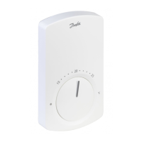
| Temperature Range | 5°C to 30°C |
| Mounting Type | Wall |
| Setpoint Adjustment | Dial |
| Application | Room Heating |