AKD 2800
Programming
Function:
This is where to choose the function of the frequency
converter after the output frequency has become
lower than the value in parameter 123 The min.
frequency for activation of function at stop or after
a stop command and when the output frequency
has been ramped down to 0 Hz.
Description of choice:
Select Coasting [0] if the frequency converter is to
’let go’ of the motor (inverter turned off).
Select DC hold [1] if parameter 137 DC hold
voltage is to be activated.
126 DC brake time
(DC BRAKING TIME)
Value:
0 - 60 sec.
✭ 10 sec
Function:
In this parameter, the DC brake time is set at which
parameter 132 DC brake voltage is to be active.
Description of choice:
Set the required time.
127 DC brake cut-in frequency
(DC BRAKE CUT-IN)
Value:
0.0 (OFF) - par. 202
Output frequency high limit, f
MAX
✭ OFF
Function:
In this parameter, the DC brake cut-in frequency
is set at which the DC brake is to be activated in
connection with a stop command.
Description of choice:
Set the required frequency.
128 Thermal motor protection
(MOT.THERM PROTEC)
Value:
✭No protection (NO PROTECTION)
[0]
Thermistor warning
(THERMISTOR WARN)
[1]
Thermistor trip (THERMISTOR TRIP)
[2]
ETR warning 1 (ETR WARNING 1)
[3]
ETR trip 1 (ETR TRIP 1)
[4]
ETR warning 2 (ETR WARNING 2)
[5]
ETR trip 2 (ETR TRIP 2)
[6]
ETR warning 3 (ETR WARNING 3)
[7]
ETR trip 3 (ETR TRIP 3)
[8]
ETR warning 4 (ETR WARNING 4)
[9]
ETR trip 4 (ETR TRIP 4)
[10]
Function:
The frequency converter can monitor the motor
temperature in two different ways:
- Via a PTC thermistor that is mounted on the motor.
The thermistor is connected between terminal 50
(+10V) and one of the digital input terminals 18, 19,
27 or 29. See parameter 300 Digital inputs.
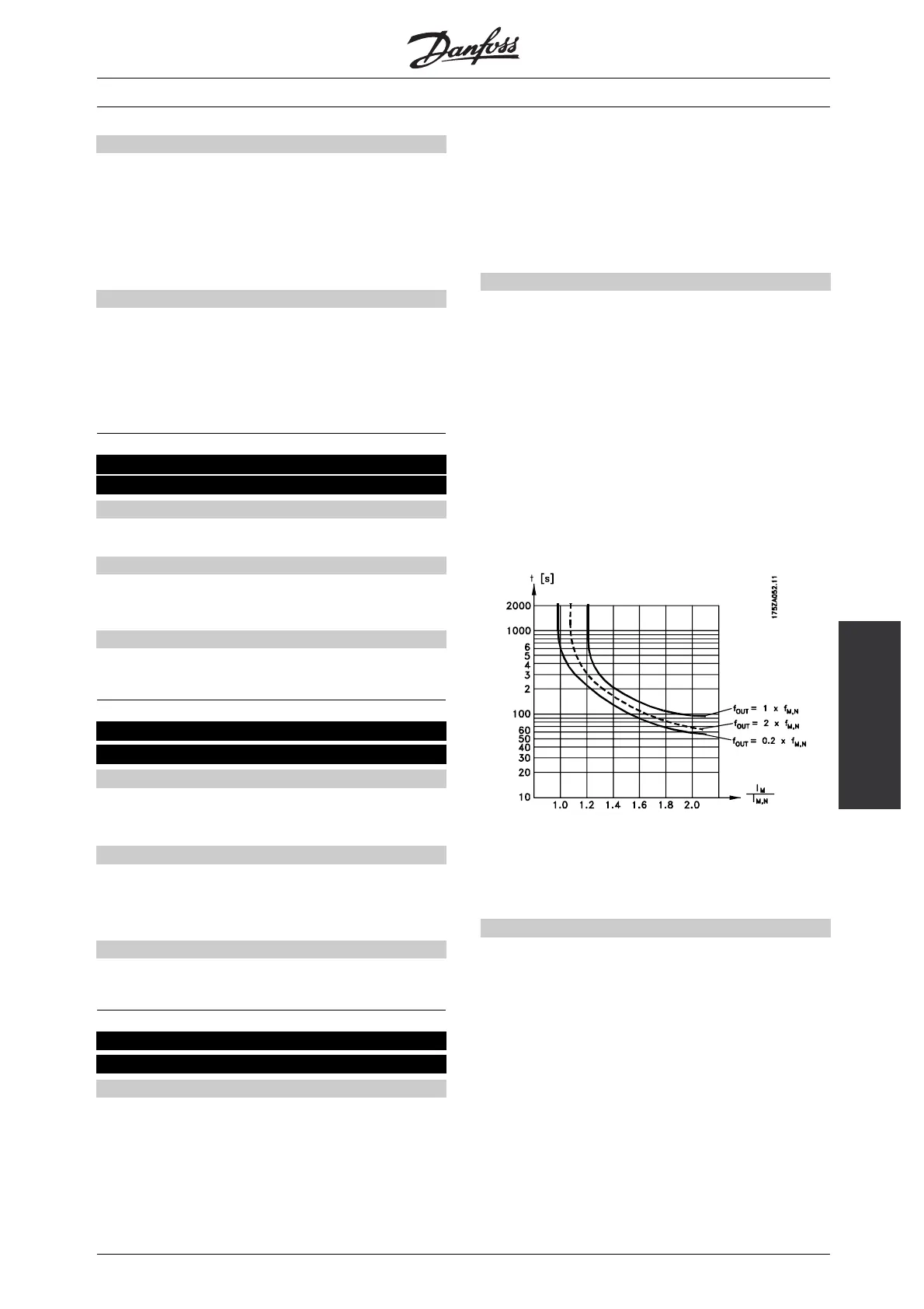
- Thermal load calculation (ETR - Electronic
Thermal Relay), based on present load and
time. This is compared with the rated motor
current I
M,N
and rated motor frequency f
M,N
.
The calculations take into account the need for
lower loading at low speeds due to the motor’s
internal ventilation being reduced.
ETR functions 1-4 do not begin to calculate the load
until you switch to the Setup in which they have been
selected. This means that you can use the ETR function
even when changing between two or more motors.
Description of choice:
Select No protection [0]ifyoudonotwantawarning
or trip when a motor is overloaded.
Select Thermistor warning [1] if you want a warning
when the connected thermistor becomes too hot.
Select Thermistor trip [2] if you want a trip when the
connected thermistor becomes too hot.
Select ETR Adv. ifyouwantawarningwhenthe
motor is overloaded according to the calculations.
You can also programme the frequency converter to
give a warning signal via the digital output.
Select ETR Trip if you want a trip when the motor is
overloaded according to the calculations.
Select ETR warning 1-4 if you want a warning when
the motor is overloaded according to the calculations.
✭
= factory setting. () = display text [] = value for use in communication via serial communication port
MG.28.H2.02 -
21