EasyManua.ls Logo

Danfoss AME 25 SU

Danfoss AME 25 SU
16 pages
To Next Page IconTo Next Page
Loading...
© Danfoss | 2016.12
VI.AD.B3.8C | 1
ENGLISH
AME 25 SU, AME 25 SD www.danfoss.com Page 6
DANSK
AME 25 SU, AME 25 SD www.danfoss.dk Side 7
DEUTSCH
AME 25 SU, AME 25 SD
www.danfoss.de Seite 8
FRANÇAIS
AME 25 SU, AME 25 SD
www.danfoss.fr Page 9
ESPAÑOL
AME 25 SU, AME 25 SD www.danfoss.es Página 10
SUOMI
AME 25 SU, AME 25 SD www.danfoss.fi Sivu 11
NEDERLANDS
AME 25 SU, AME 25 SD www.danfoss.nl Bladzijde 12
POLSKI
AME 25 SU, AME 25 SD www.danfoss.pl Strona 13
中文
AME 25 SU, AME 25 SD www.danfoss.com.cn 14
РУССКИЙ
AME 25 SU, AME 25 SD www.danfoss.ru Страница 15
AME 25 SU, AME 25 SD
Operating Guide
AME 25 SD / SU +
Adapter (065Z0311) +
VRB 2, VRG 2 (DN 15-50)
AME 25 SD / SU +
Adapter (065Z0311) +
VF 2, VL 2 (DN 15-50)
AME 25 SD / SU +
Adapter (065Z0311) +
VRB 3, VRG 3 (DN 15-50)
AME 25 SD / SU +
Adapter (065Z0311) +
VF 3, VL 3 (DN 15-50)
AME 25 SD / SU +
VFS 2 (DN 15-50)
Question and Answer IconNeed help?

Do you have a question about the Danfoss AME 25 SU and is the answer not in the manual?

Danfoss AME 25 SU Specifications

General IconGeneral
BrandDanfoss
ModelAME 25 SU
CategoryDC Drives
LanguageEnglish

Summary

Assembly and Safety

Safety Symbols and Warnings

Key safety symbols and warnings for actuator operation and maintenance.

Installation Procedure

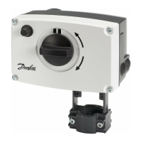
Illustrated guide to physically installing the actuator onto the valve.

Wiring Configurations

Modulating Mode Wiring

Electrical diagram for actuator operation in modulating control mode.

3-Point Floating Mode Wiring

Electrical diagrams for 3-point floating control with relay or triac output.

Control Signals and DIP Switch Settings

Signal Behavior Diagrams

Diagrams showing actuator response to various control input signals.

DIP Switch Functionality

Explanation of DIP switch functions for actuator configuration and operation.

Technical Specifications

Adapter and Valve Compatibility

Details on compatible adapters for different valve types and sizes.

Dimensional Data

Physical dimensions and connection sizes for actuator models.

Operational Guidance and Precautions

Safety, Disposal, and Mounting

Critical safety notes, disposal instructions, and mounting guidelines.

Operation and Testing Overview

Summary of control signals, output signals, DIP switches, and function test.

Related product manuals