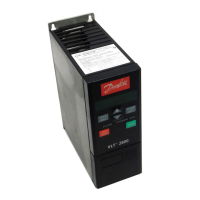
AKD 2800
All about AKD
2800
LED indication
Warning yellow
Alarm red
Trip locked yellow and red
WARNING/ALARM 2: Live zero fault
The voltage or current signal on terminal 53 or
60 is below 50% of the preset value in parameter
309 or 315 Terminal, min. scaling.
WARNING/ALARM 4: Mains phase fault
No phase on mains supply side. Check the supply
voltage to the frequency converter. This fault is only
active in 3-phase mains supply. The alarm can also
occur when the load is pulsing. In this instance the
pulses must be dampened, e.g. using an inertia disc.
WARNING 5: Voltage warning high
If the intermediate circuit voltage (UDC) is higher than
Voltage warning high the frequency converter will
give a warning and the motor will continue to run
unchanged. If the UDC remains above the voltage
warning limit, the inverter will trip after a set time.
The time depends on the device, and is set at 5 - 10
sec. Note: The frequency converter will trip with an
alarm 7 (overvoltage). A voltage warning can occur
when the connected mains voltage is too high. Check
whether the supply voltage is suitable for the frequency
converter, see Technical data. A voltage warning can
also occur if the motor frequency is reduced too quickly
due to ramp down time being too short.
WARNING 6: Voltage warning low
If the intermediate circuit voltage (UDC) is lower than
Voltage warning low the frequency converter will give a
warning and the motor will continue to run unchanged.
A voltage warning can occur when the connected
mains voltage is too low. Check whether the supply
voltage is suitable for the frequency converter, see
Technical data. When the frequency converter is
switched off a brief warning 6 (and warning 8) appears.
WARNING/ALARM 7: Overvoltage
If the intermediate voltage (UDC) goes over the
inverter’s Overvoltage limit theinverterwillbeswitched
off until the UDC has once more fallen below the
overvoltage limit. If the UDC remains above the
overvoltag limit the inverter will trip after a set time. The
time depends on the device, and is set at 5 - 10 sec.
An overvoltage in the UDC can occur when the motor
frequency is reduced too quickly due to ramp down
time being too short. When the inverter is switched off
a trip reset is generated. Note: Voltage warning high
(warning 5) will thus also be able to generate an alarm 7.
WARNING/ALARM 8: Undervoltage
If the intermediate circuit voltage (UDC) is lower than
the inverter’s Undervoltage limit the inverter will be
switched off until the UDC once more goes above
the undervoltage limit. If the UDC remains under the
undervoltage limit, the inverter will trip after a set time.
The time depends on the device, and is set at 2 - 15
sec. An undervoltage can occur when the connected
mains voltage is too low. Check whether the supply
voltage is suitable for the frequency converter, see
Technical data. When the frequency converter is
switched off a alarm 8 (and alarm 6) is displayed briefly
and a trip reset is generated. Note: Voltage warning low
(warning 6) will thus also be able to generate an alarm 8.
WARNING/ALARM 9: Inverter overload
Electronic thermal inverter protection indicates that
the frequency converter is close to tripping due to
overloading (output current too high for too long). The
counter for electronic thermal inverter protection gives a
warning at 98% and trips at 100% accompanied by an
alarm. The frequency converter cannot be reset until the
counter drops below 90%. This fault arises because the
frequency converter has been overloaded for too long.
WARNING/ALARM 10: Motor overloaded
According to the electronic thermal inverter protection
the motor is too hot. In parameter 128 the user can
select whether the frequency converter should emit
a warning or an alarm when the counter reaches
100%. This fault is due to the motor being overloaded
by more than 100% for too long. Check that motor
parameters 102-106 are set correctly.
WARNING/ALARM 11: Motor thermistor
The motor is too hot or the thermistor/thermistor
connection has been disconnected. In parameter
128 Thermal motor protection the user can select
whether the frequency transformer emits a warning or
an alarm. Check that the PTC thermistor is correctly
connected between terminals 18, 19, 27 or 29 (digital
input) and terminal 50 (+ 10 V supply).
WARNING/ALARM 12: Current limit
The output current is greater than the value in
parameter 221 Current Limit
LIM
, and the frequency
converter will trip after a set time, selected in
parameter 409 Trip delay overcurrent.
WARNING/ALARM 13: Overcurrent
The inverter’s peak current limit (approx. 200%
of rated output current) has been exceeded. The
warning will last approx. 1-2 sec, and the frequency
converter will then trip and emit an alarm. Switch
MG.28.H2.02 -
59
 Loading...


