176FA246.10
U/T1 96
-DC 88
R/L1 91
S/L2 92
T/L3 93
+DC 89
V/T2 97
W/13
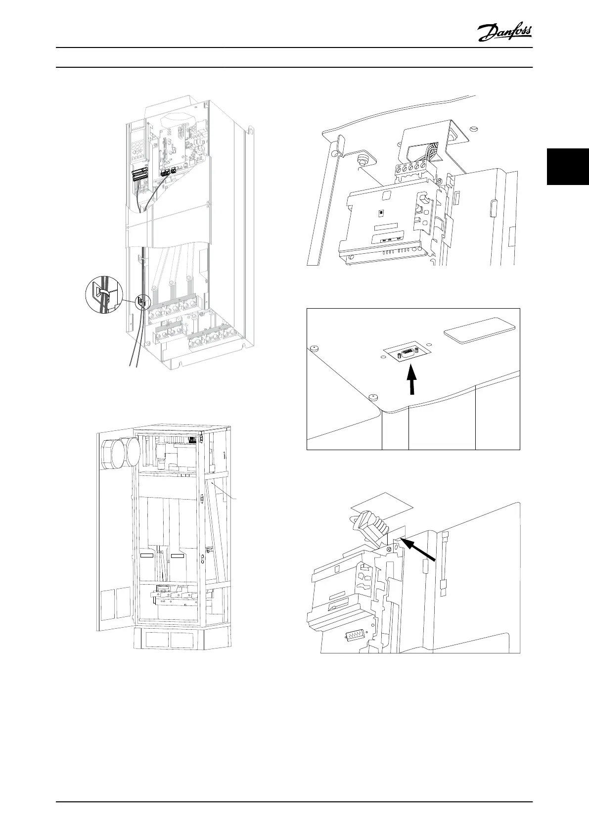
Illustration 3.65 Control Card Wiring Path for the D3. Control
Card Wiring for the D1, D2, D4, E1 and E2 use the same Path
Illustration 3.66 Control Card Wiring Path for the F1/F3.
Control Card Wiring for the F2/F4 use the same Path
In the Chassis (IP00) and NEMA 1 units, it is also possible
to connect the fieldbus from the top of the unit as shown
in the following pictures. On the NEMA 1 unit a cover
plate must be removed.
Kit number for fieldbus top connection: 176F1742
130BA867.10
Probus Option A
FC300 Service
Illustration 3.67 Top Connection for Fieldbus.
Illustration 3.68
Illustration 3.69
How to Install
VLT
®
Automation Drive FC 300 Operating Instructions
MG33U402 - Rev. 2013-12-16 71
3 3
 Loading...


