0.0 [0.00]
134.6 [5.30]
104.3 [4.11]
0.0 [0.00]
179.3 [7.06]
219.6 [8.65]
294.6 [11.60]
334.8 [13.18]
409.8 [16.14]
436.9 [17.20]
0.0 [0.00]
532.9 [20.98]
0.0 [0.00]
44.4 [1.75]
244.4 [9.62]
154.0 [6.06]
344.0 [13.54]
1
2
3
4
5
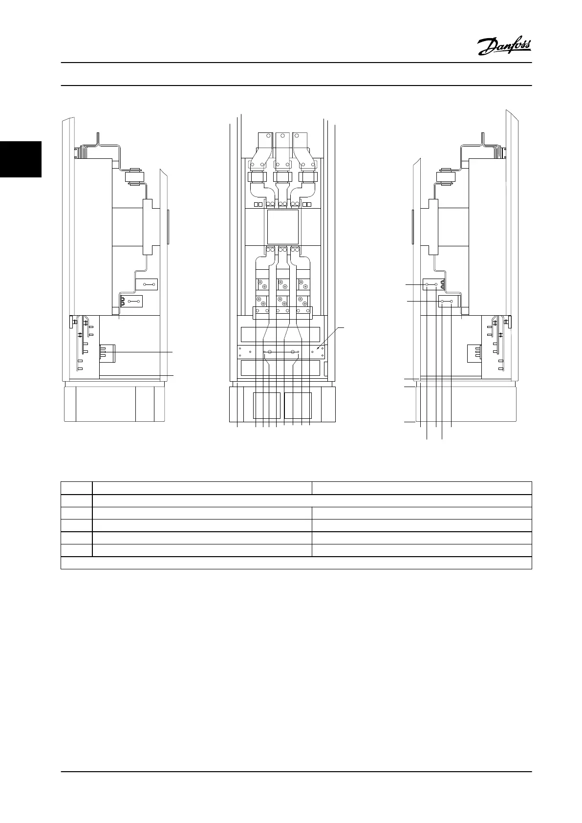
130BA852.11
500 kW
1)
(mm [in.]) 560–710 kW
1)
(mm [in.])
1 Ground bar
2 34.9 [1.4] 46.3 [1.8]
3 86.9 [3.4] 98.3 [3.9]
4 122.2 [4.8] 119 [4.7]
5 174.2 [6.9] 171 [6.7]
1) Disconnect location and related dimensions vary with kilowatt rating.
Figure 3.16 Input Option Cabinet with Circuit Breaker, Enclosure Size F18
The gland plate is 42 mm below the 0 level. Shown are the left side view, front, and right.
Installation
VLT
®
AutomationDrive FC 302 Low Harmonic Drive
132–630 kW
32 Danfoss A/S © Rev. 04/2015 All rights reserved. MG37A322
33
 Loading...


