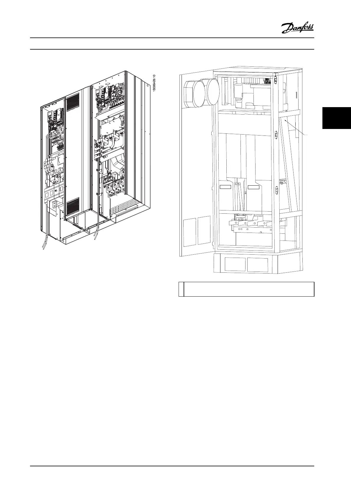
Figure 4.7 Control Card Wiring Path for Frame Size E9
1 Routing path for the control card wiring, inside the adjustable
frequency drive enclosure.
Figure 4.8 Control Card Wiring Path for Frame Size F18
4.8.2 Access to Control Terminals
All terminals to the control cables are located beneath the
LCP (both lter and adjustable frequency drive LCP). They
are accessed by opening the door of the unit.
4.8.3 Electrical Installation, Control
Terminals
To connect the cable to the terminal:
1. Strip insulation by about 0.35–0.4 in [9–10 mm]
Electrical installationControl terminals
Electrical Installation Installation Manual
MG37A322 Danfoss A/S © Rev. 04/2015 All rights reserved. 43
4 4
 Loading...


