-
-
-
•
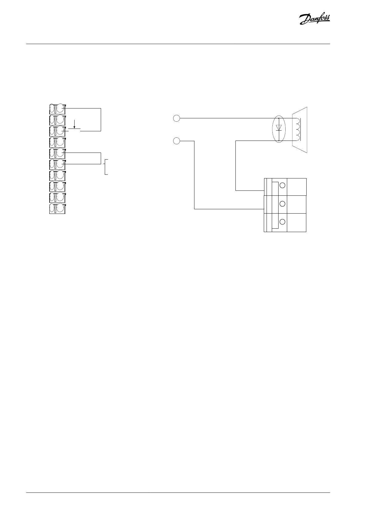
Parameter 5-12 Terminal 27 Digital Input to [2] Coasting Stop, Inverse.
Parameter 5-02 Terminal 29 Mode to [1] Terminal 29 Mode Output.
Parameter 5-31 Terminal 29 Digital Output to [27] Torque limit & stop.
Connect to relay output 1 (XD2.21). Then set parameter 5-40 Function Relay to [32] Mechanical Brake Control.
+24 V DC
P 5-10 [8]
P 5-12 [2]
P 5-02 [1]
P 5-31 [27]
GND
P 5-40 [0] [32]
Relay 1
-
+
e30bu096.10
XD2.19
XD2.18
XD2.17
XD2.16
XD2.15
XD2.14
XD2.13
XD2.12
XD2.11
XD2.10
24 V DC
Mechanical brake connection
I
Illustration 73: Wire Configuration for Torque and Stop Limit
AQ262139143212en-000301 / 130R0879136 | Danfoss A/S © 2021.10
Wiring Configuration Examples
VLT® AutomationDrive FC 302
Operating Guide