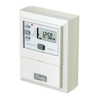
The ECL Comfort 100M is a sophisticated controller designed by Danfoss for the automatic temperature regulation of heating systems, offering a blend of energy efficiency, enhanced comfort, and ease of use. This device is engineered to optimize heating control, adapting to various environmental conditions and user preferences to ensure an ideal indoor climate while minimizing energy consumption.
Function Description
The primary function of the ECL Comfort 100M is to provide precise and automatic temperature control for heating circuits. It achieves this through a combination of sensor inputs, user-defined settings, and intelligent algorithms. The controller monitors both outdoor and, optionally, indoor temperatures to adjust the flow temperature of the heating system, ensuring that the desired comfort level is maintained without unnecessary energy expenditure.
One of its core features is "weather compensation," which allows the controller to anticipate heating needs based on changes in outdoor temperature. This proactive approach prevents over- or under-heating, contributing significantly to energy savings. The controller uses a user-definable heat curve to determine the appropriate flow temperature for varying outdoor conditions.
The ECL Comfort 100M can operate in different modes:
- Manual operation: This mode is primarily for maintenance and service, allowing direct control over the heating system. It's important to note that frost protection is switched off in this mode.
- Constant comfort temperature: In this mode, the system maintains a continuous comfort temperature, disregarding any programmed day plans. This is useful for extended periods when a higher temperature is desired, such as during a day off or a late-night event.
- Automatic operation: This is the standard mode. If an analog clock is installed, the controller follows a programmed day plan, automatically switching between comfort and reduced temperatures. Without a clock, it maintains a constant comfort temperature.
- Constantly reduced temperature: This mode is ideal for periods when the premises are unoccupied, such as during holidays, as it maintains a lower, energy-saving temperature.
- Standby: In this mode, heating is stopped, but the system remains protected against frost. This is typically used during warmer months.
The controller also incorporates an automatic pump motion program, which periodically activates the circulation pump to prevent it from blocking due to inactivity, thereby extending its lifespan and ensuring system reliability.
For systems with multiple controllers, the ECL Comfort 100M supports master/slave configurations via the ECL Comfort BUS. In such setups, a master controller, physically connected to the outdoor sensor, shares outdoor temperature information with slave controllers, allowing for synchronized and efficient heating across a larger system. Slave controllers can also send reference temperature demands to the master.
Usage Features
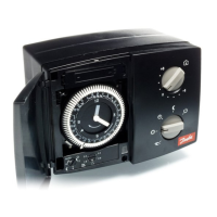
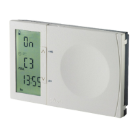
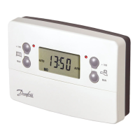
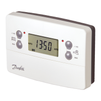
The ECL Comfort 100M is designed for intuitive user interaction, primarily through its front panel controls and an optional analog clock.
- Setting the clock (optional): When an analog clock is mounted, users can set the actual week day and time by turning the minute hand. The outer ring of the clock, which includes sliders, allows users to define individual comfort and reduced temperature periods. Sliders pointing towards the center indicate comfort temperature, while those pointing outwards signify reduced temperature. This enables personalized heating schedules throughout the week. The clock also requires manual adjustment for summer and winter time changes.
- Temperature setting: The controller features a temperature setting button. If a room sensor is installed, the midpoint of this button corresponds to 20 °C, allowing users to set the room temperature within a range of 12 to 28 °C. Without a room sensor, this button adjusts the flow temperature, which approximates a change in room temperature of +/- 8 °C. Adjustments can be made to achieve the desired comfort temperature, with guidance provided for troubleshooting scenarios where the target temperature isn't met (e.g., checking radiator thermostat settings or increasing flow temperature).
- Temperature reduction: A dedicated knob (potentiometer) allows users to select the desired temperature reduction during reduced temperature periods. Options include fixed temperature reductions (1-14 degrees) or an "AUTO" setting for variable reduction, which adapts based on outdoor temperature (not reducing if outdoor temperature is below -8 °C). The "standby" position stops heating while maintaining frost protection.
- Setting the heat curve: The heat curve defines the relationship between outdoor temperature and the required flow temperature of the heating circuit. Users can adjust the slope of this curve within a range of 0.2 to 2.2, with a factory setting of 1.2. This allows for fine-tuning the system's response to outdoor conditions, optimizing comfort and energy use for different building types (e.g., radiator circuits vs. floor heating).
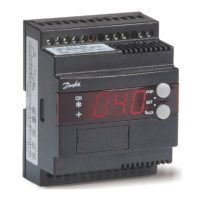
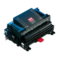
- Controller settings on the rear side: For initial setup and advanced configuration, the controller has mini switches (1 to 8) on its rear side. These switches allow for critical adjustments:
- Switch 1 (Heating cut-out): Sets the outdoor temperature limit at which the heating system stops, helping to save energy.
- Switch 2 (Minimum flow temperature limit): Defines the acceptable minimum flow temperature in the heating system.
- Switch 3 (Maximum flow temperature limit): Establishes a maximum flow temperature to prevent system overheating.
- Switch 4 (Running time of the motorized valve): Configures the running time of the motorized valve (20 or 120 seconds), which is the time it takes for the valve to move from closed to fully open. This setting is disabled if a thermo actuator is selected via switch 5.
- Switch 5 (Gear motor/thermo actuator): Selects between a gear motor or a thermo actuator, depending on the heating system's components.
- Switches 6, 7, and 8 (Addressing and time unit selection): These switches are used to set the slave address of the controller in a master/slave system or to configure the address of an ECA 60/61 unit if connected.
Maintenance Features
The ECL Comfort 100M includes features and guidelines to ensure its longevity and reliable operation.
- Power back-up: The controller is equipped with a battery (Alkaline AAA 1.5 V type) for power back-up, located above the clock. Although not always in operation, Danfoss recommends replacing this battery every two years to ensure continuous timekeeping and program retention during power outages. The battery holder is easily removable for replacement.
- Sensor placement guidelines: Proper sensor installation is crucial for accurate temperature control.
- Outdoor temperature sensor (ESMT type): Should be mounted on the north side of the building, away from direct sunlight, doors, or windows, to ensure it measures ambient outdoor temperature accurately.
- Flow temperature sensor (ESMU, ESM-11, or ESMC types): Should be placed within 15 cm of the mixing point. For systems with heat exchangers, the ESMU-type is recommended for insertion into the exchanger flow outlet. The pipe surface must be clean where the sensor is mounted. For ESM-11 sensors, it's important not to move them after fastening to avoid damaging the sensor element.
- Room temperature sensor (ESM-10, ECA 60, and 61 remote controls): Should be placed in the room where temperature control is desired, avoiding outside walls, radiators, windows, or doors to prevent skewed readings.
- Electrical connections: Detailed diagrams are provided for both 230 V a.c. and 24 V a.c. connections, including terminal descriptions and maximum loads for various components like gear motors, circulation pumps, and relays. Specific jumper configurations are outlined for proper setup. Users are warned about the importance of correct wiring to prevent damage to TRIAC outlets.
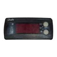
- LED indication and function test: The controller features an LED indicator that provides visual feedback on its operational status and helps in troubleshooting.
- Control status: During normal operation, the LED lights up continuously or with interruptions, indicating whether the flow temperature is in the neutral zone, or if the motor is opening or closing the valve.
- Function test: By turning the function switch to a specific position, a self-test can be initiated. After a few seconds, the LED will flash to show the test result. No light indicates a defective controller or unmounted flow temperature sensor. Flashing with 1, 2, or 3 intervals corresponds to the number of connected sensors, helping to identify short-circuited or disconnected sensors.
- Checklist: A comprehensive checklist is provided to ensure the controller is ready for use, covering aspects like correct power supply wiring, rear-side settings, proper connection of pumps and valves, sensor connections, and verification of motorized valve turning direction. This systematic approach helps in confirming the correct installation and functionality of the system.