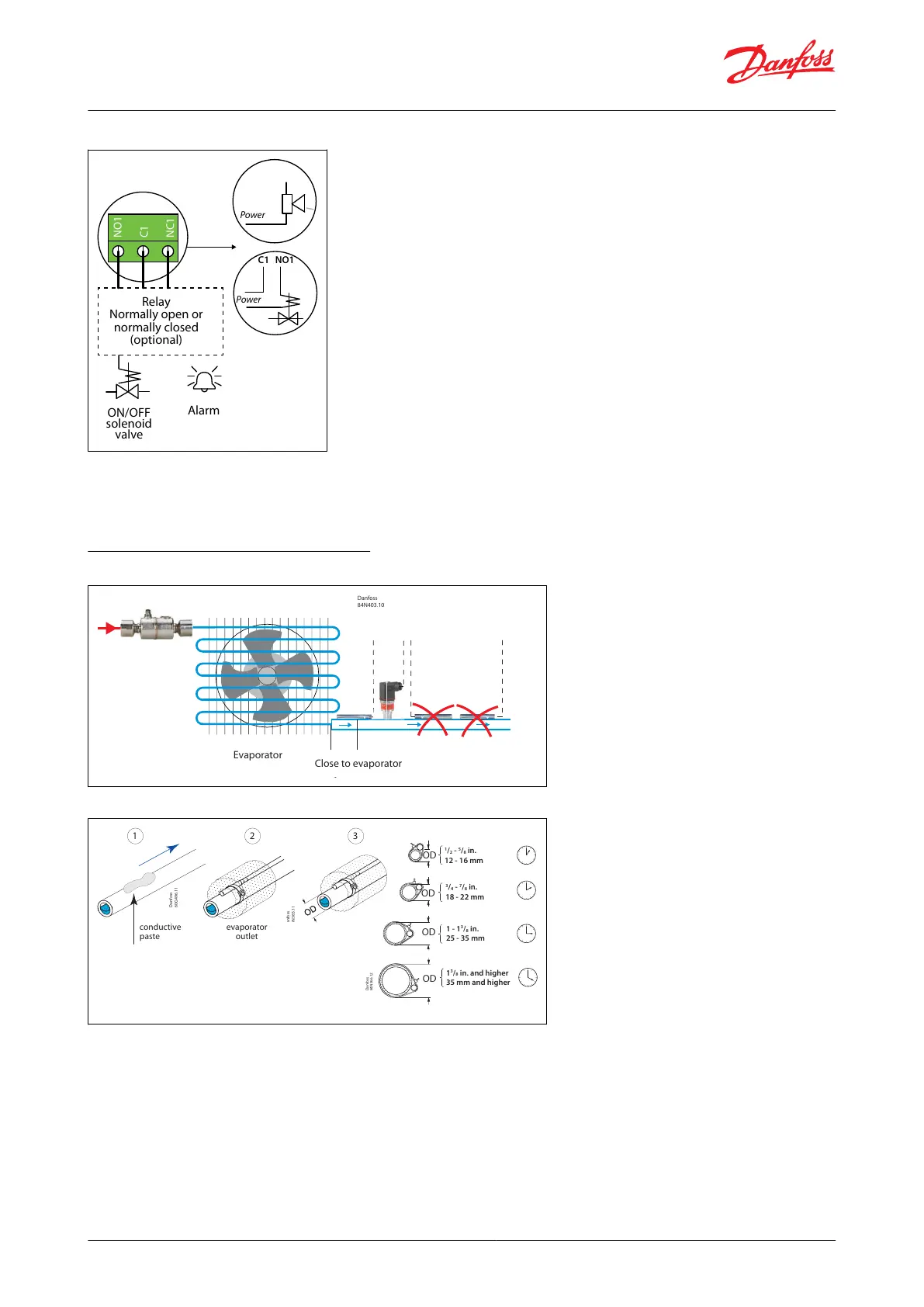
Figure 11: Temperature sensor mounting
Evaporator
Danfoss
84N403.10
Close to the
evaporat or
Close to evaporator
Figure 10: SPDT relay
NO1
C1
NC1
NO1
C1
NC1
C1 NO1
Power
Power
ON/OFF
solenoid
valve
Alarm
Relay
Normally open or
normally closed
(optional)
NOTE:
The relays cannot be used for the direct connection of loads such as LEDs and ON/OFF control of EC motors. All
loads with a switch-mode power supply must be connected to a suitable contactor or similar
3.6 Temperature Sensor Mounting
Figure 12: Temperature sensor mounting
Danfoss
60G496.11
OD
OD
OD
OD
1
/
2
-
5
/
8
in.
12 - 16 mm
3
/
4
-
7
/
8
in.
18 - 22 mm
1 - 1
3
/
8
in.
25 - 35 mm
1
3
/
8
in. and higher
35 mm and higher
Danf
oss
84N366.12
21
conductive
paste
evaporator
outlet
NOTE:
• Mount sensor on a clean surface without any paints
• Remember to put on heat conducting paste and insulate the sensor
• Sensor mounting max. 5 cm from the outlet of the evaporator
• Physical temperature sensor can’t be shared
NOTE:
Installation of the pressure transmitter is less critical. but mounting of pressure transmitter should be closer to the
temperature sensor right after the evaporator and with its head in “upright position
© Danfoss | Climate Solutions | 2022.06 BC398828796060en-000101 | 15
Superheat controller, Type EKE 1A, 1B, 1C, 1D