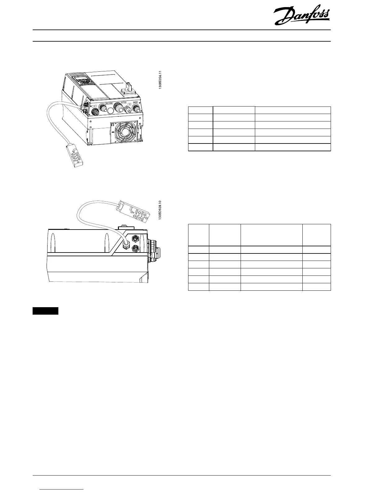
FC 302 with MCO - mains connectors and 4 cable glands
(134N8410)
Illustration 3.3 Mains Connectors and 4 Cable Glands
FC 302 with connectors - side view
Illustration 3.4 Side View
NOTICE
See the VLT
®
AutomationDrive FC 301/FC 302 Design Guide
for dimensions and further information.
Connectors
Overview
The frequency converter has 7 connectors plus 2 or 4 motor
connectors.
Label Connector Description
X1 Mains Mains in M23 (in M25) Male
X2.1-X2.4 Motor Motor connection M23 Female
X51 PROFIBUS - Male PROFIBUS M12
X52 PROFIBUS - Female PROFIBUS M12
X11-X14 I/O box connector Phoenix I/O box
Table 4.1 Connectors
X1- Mains M23 (in M25) Male
General ratings
•
Pins 1, 2, 3, and 4: 480 V AC, maximum 15 A.
•
Pins C and D: 30 V DC, maximum 3 A.
•
Tightening torque: 1.5–2.0 Nm (13.3–17.7 in-lb)
Pin Label Connected to frequency
converter wiring schematic
Minimum
wire [mm
2
(AWG)]
1 T1 91 (L1) 2.5 (14)
4 T2 92 (L2) 2.5 (14)
3 T3 93 (L3) 2.5 (14)
2 PE 95 (PE) 2.5 (14)
D 0 V DC 35 0.75 (18)
C 24 V DC 36 0.75 (18)
Table 4.2 Wire/Connector Assignment for Plug X1
Mating part: Mains X1 (female)
Phoenix ordering number: KK-0885/XX,XX
Installation Instructions VLT® AutomationDrive FC 302 with Connectors
2
Danfoss A/S © 11/2015 All rights reserved. MI04G402