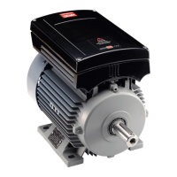
Overview of Marking and Cable Glands
(134N8410)
Marking Type of cable gland
Allowed cable
diameter [mm (in)]
Encoder EMC M20x1,5 7.5–14.0 7.5–14.0 (0.3–0.55)
Motor EMC M25x1,5 10.0–18.0 10.0–18.0 (0.4–0.7)
Brake EMC M20x1,5 7.5–14.0 7.5–14.0 (0.3–0.55)
I/O M25x1.5 50.625 (plastic RAL 7035) 11–16 (0.45–0.6)
Table 4.9 Cable Glands (134N8410)
Installation
NOTICE
For installation, refer to the VLT
®
AutomationDrive FC 301/FC
302 Operating Instructions.
NOTICE
For installation of 134N8410 FC 302 with MCO, also refer to
the VLT
®
Motion Control Option MCO 305 Operating
Instructions.
Danfoss can accept no responsibility for possible errors in catalogues, brochures and other printed material. Danfoss reserves the right to alter its products without notice. This also applies to products already on
order provided that such alterations can be made without subsequential changes being necessary in specifications already agreed. All trademarks in this material are property of the respective companies. Danfoss
and the Danfoss logotype are trademarks of Danfoss A/S. All rights reserved.
Danfoss A/S
Ulsnaes 1
DK-6300 Graasten
vlt-drives.danfoss.com
*MI04G402*
MI04G402130R0611 11/2015
 Loading...


