FCM 300 Series
MG.03.B6.02 - VLT is a registered Danfoss trademark36
Function/settingsFunction/settings
Function/settingsFunction/settings
Function/settings
Key (Start)Key (Start)
Key (Start)Key (Start)
Key (Start)
Key (Start)Key (Start)
Key (Start)Key (Start)
Key (Start)
Key (Stop)Key (Stop)
Key (Stop)Key (Stop)
Key (Stop)
Default - Dual speed operationDefault - Dual speed operation
Default - Dual speed operationDefault - Dual speed operation
Default - Dual speed operation Run on set Run on Stop (and
(connect purple wire):(connect purple wire):
(connect purple wire):(connect purple wire):
(connect purple wire): reference 10 Hz** reset* - if trip)
No changes to factory setting. (+/-) jog speed
Function 2 - Dual mode operationFunction 2 - Dual mode operation
Function 2 - Dual mode operationFunction 2 - Dual mode operation
Function 2 - Dual mode operation
(connect purple wire):(connect purple wire):
(connect purple wire):(connect purple wire):
(connect purple wire): Run with Run with Stop (and
Select desired modes of operation Setup 1 Setup 2 reset* - if trip)
in Setups 1 and 2 (use para. 4-6)
Parameter 335 = 18 (select Setup)
Function 3 - Dual direction operationFunction 3 - Dual direction operation
Function 3 - Dual direction operationFunction 3 - Dual direction operation
Function 3 - Dual direction operation
(connect grey wire):(connect grey wire):
(connect grey wire):(connect grey wire):
(connect grey wire): Run Run Stop (and
Parameter 335 = 10 (start reversing) forward reverse reset* - if trip)
Parameter 200 = 1 (both directions)
*If no reset is required,
do not connect the brown wire
**or set parameter 213
At power up the unit will always be in stop mode.
Set reference will be stored during power down. If
permanent start mode is desired, connect terminal
6 to terminal 4 and do not connect purple/grey
wire to terminal 4. This means the stop function on
LOP is disabled.
NB!NB!
NB!NB!
NB!
After fitting, cut off or isolate excess wire.
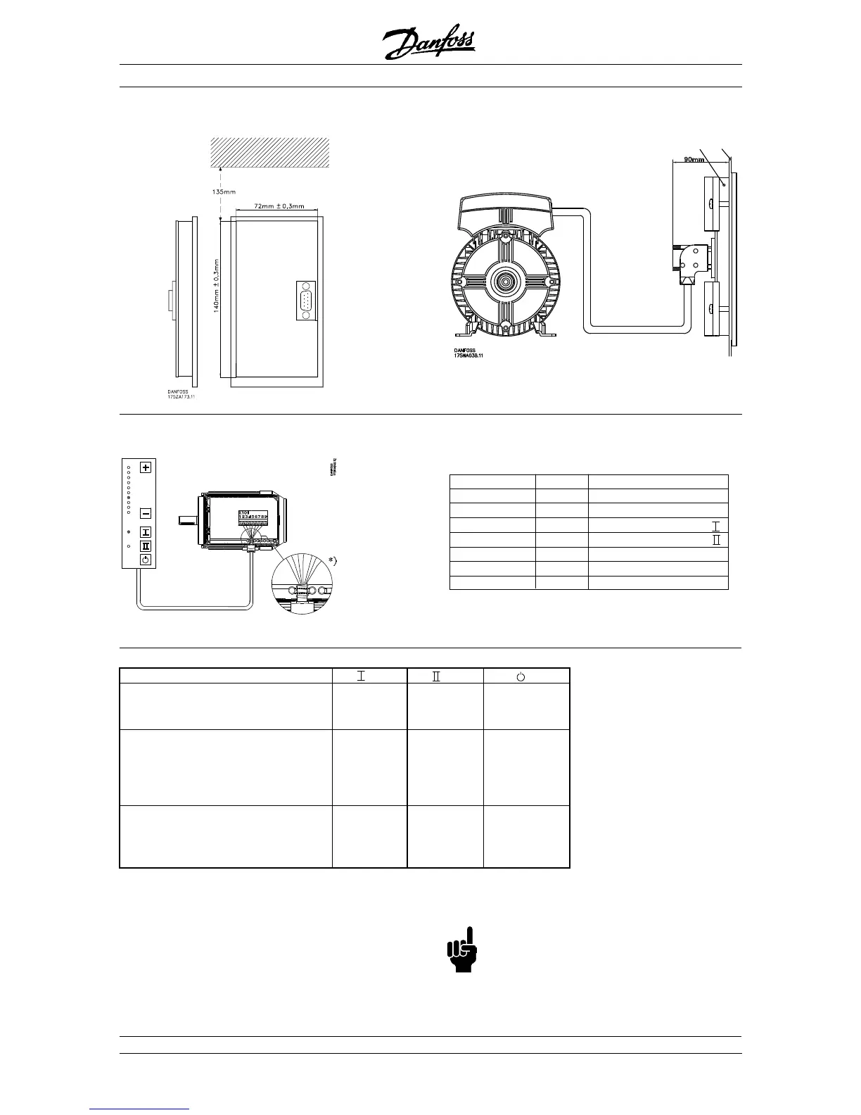
Local Control
Use the +/- keys to set reference
Colour of wireColour of wire
Colour of wireColour of wire
Colour of wire
TT
TT
T
erminalerminal
erminalerminal
erminal
FunctionFunction
FunctionFunction
Function
White 2 Reference
Brown 3 Reset
Purple or Grey 4 See table under button
Green 5 See table under button
Red 6 +24V
Yellow 7 +10V
Blue 8 Ground
WW
WW
W
iringiring
iringiring
iring
■ Local Operation Pad (LOP)
■ Remote mounting kit cont.
Panel
door
Control unit

 Loading...