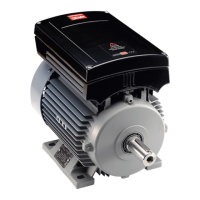
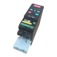
FCM 300 Series
71
MG.03.B6.02 - VLT is a registered Danfoss trademark
✭ = factory setting. ( ) = parameter window text. [ ] = value for use in communication via serial communication port
617 Fault log: Value
(F.LOG: VALUE)
Value:
[Index XX - XXX]
Function:
Array type parameter. This parameter makes it
possible to see at what current or voltage a given trip
occurred.
Description of choice:
Read out as one value.
Indication range: 0.0 - 999.9.
The fault log is reset after initialisation (para. 620).
619 Reset of hours-run counter
(RESET RUN. HOUR)
Settings:
★ No reset (DO NOT RESET) [0]
Reset (RESET COUNTER) [1]
Function:
Reset to zero of hours-run counter (parameter 601).
Description of choice:
If Reset [1] has been selected the hours-run counter
of the FC motor is reset.
620 Operating mode (OPERATION MODE)
Settings:
★ Normal function (NORMAL OPERATION) [0]
Control card test (CONTROL CARD TEST) [2]
Initialisation (INITIALIZE) [3]
Function:
In addition to its normal function, this parameter can
be used for two different tests.
Also, all parameters (except parameters 603-605) can
be initialised.
Description of choice:
Normal function [0] is selected for normal operation
with the motor in the selected application.
Technical functions
621 Nameplate: FC type (FC TYPE)
Value:
Depends on unit
Function:
The key data of the unit can be read out via the serial
communication port.
Description of choice:
Type indicates the unit size and basic function
concerned.
624 Nameplate: Software version no.
(SOFTWARE VERSION)
Value:
Depends on unit
Function:
The key data of the unit can be read out the serial
communication port.
Description of choice:
Software version gives the version number.
625 Nameplate: LCP identification no.
(LCP VERSION)
Value:
Depends on unit
Function:
The key data of the unit can be read out via the
display or the serial communication port.
For example: ID 1,42 2 kB.
Control card test [2] is selected if control of the
analogue and digital inputs, as well as the analogue,
digital outputs and the +10 V control voltage is
desired.
A test connector with internal connections is required
for this test. Setup: Analogue/digital output to digital
inputs 3, 4 and 5 and 10 V supply to analogue/digital
input 2.
Initialisation [3] is selected if the factory setting of the
unit is desired without resetting parameters 500, 501
+ 600 - 605. Initialisation is active after power up.

 Loading...


