FCM 300 Series
MG.03.B6.02 - VLT is a registered Danfoss trademark78
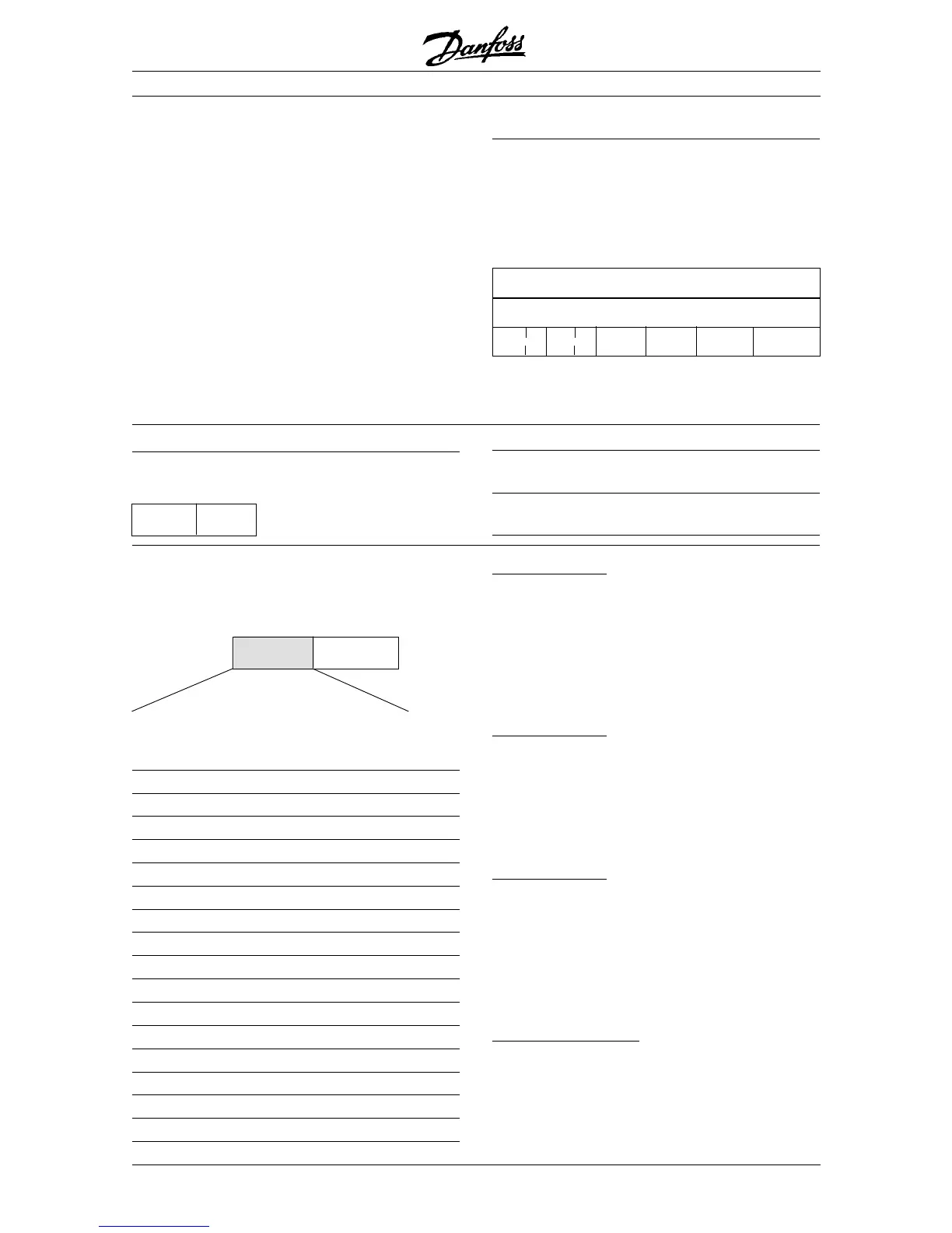
PCD1 PCD2
Control telegram Control word Reference value
(master➝slave)
Reply telegram Status word Given output
(slave➝master) frequency
2. Process-bytes
The process byte block is divided into two blocks each
of 16 bits, which always come in the sequence stated.
PCD1 PCD2
(parameter 512 = Profidrive)
The control word is used for transmitting commands
from a master (e.g. a PC) to a slave (FC motor).
Master➝Slave
1514131211109876543210Bit no.
Bit Bit = 0 Bit =1
00 OFF 1 ON 1
01 OFF 2 ON 2
02 OFF 3 ON 3
03 Motor coasting Enable
04 Quick-stop Ramp
05 Freeze output frequency Ramp enable
06 Ramp stop Start
07 No function Reset
08 Jog 1 OFF ON
09 Jog 2 OFF ON
10 Data not valid Valid
11 No function Slow down
12 No function Catch-up
13 Choice of Setup
14
15 No function Reversing
Control
word
Bus
reference
Bit 00, OFF1/ON1:
An ordinary ramp stop which uses the ramp time in
parameters 207/208. Bit 00 = "0" leads to a stop and to
output being activated, the output frequency is 0 Hz,
provided OFF 123 has been selected in parameter 340.
Bit 00 = "1" means that the frequency converter will be
able to start if the other conditions for starting have been
fulfilled.
Bit 01, OFF2/ON2:
Coasting stop. Bit 01 = "0" leads to a coasting stop
and leads to output being activated, when the output
frequency is 0 Hz, provided OFF 123 has been
selected in parameter 340. Bit 01 = "1" means that the
frequency converter is able to start, provided the other
conditions for starting are fulfilled.
Bit 02, OFF3/ON3:
Quick-stop, which uses the ramp time in parameter
212. Bit 02 = "0" leads to a quick-stop and leads to
output being activated, when the output frequency is
0 Hz, provided OFF 123 has been selected in
parameter 340. Bit 02 = "1" means that the frequency
converter is able to start, provided the other
conditions for starting are fulfilled.
Bit 03, Coasting/enable:
Coasting. Bit 03 = "0" leads to a stop. Bit 03 = "1"
means that the frequency converter is able to start,
provided the other conditions for starting are fulfilled.
Note: In parameter 502 the choice is made as to how
bit 03 is to be combined (gated) with the
corresponding function in the digital inputs.
The different attributes for each parameter can be
seen in the section on factory settings.
Since a parameter value can only be transferred as an
integer, a conversion factor must be used to transfer
decimals.
Example:
Parameter 201: minimum frequency, conversion
factor 0,1. If parameter 201 is to be set to 10 Hz, a
value of 100 must be transferred, since a conversion
factor of 0,1 means that the transferred value will be
multiplied by 0.1. A value of 100 will thus be
understood as 10.
Serial communication
Addressing by unit ID
The unit ID is printed on the label on the plastic cover
under the lid of the electronics box. The three groups
of unit ID each with three digits must be converted to
Hex. The desired address is added as the last byte.
The frame is sent to the bus address parameter(s)
500 (and 918) via a broadcast.
Unit ID: 0-255 0-255 1-255
PKE IND 00-FF 00-FF 01-FF Address
PKE: Write to parameter No. 500 or 918
IND: Not Used
➞
➞
➞

 Loading...