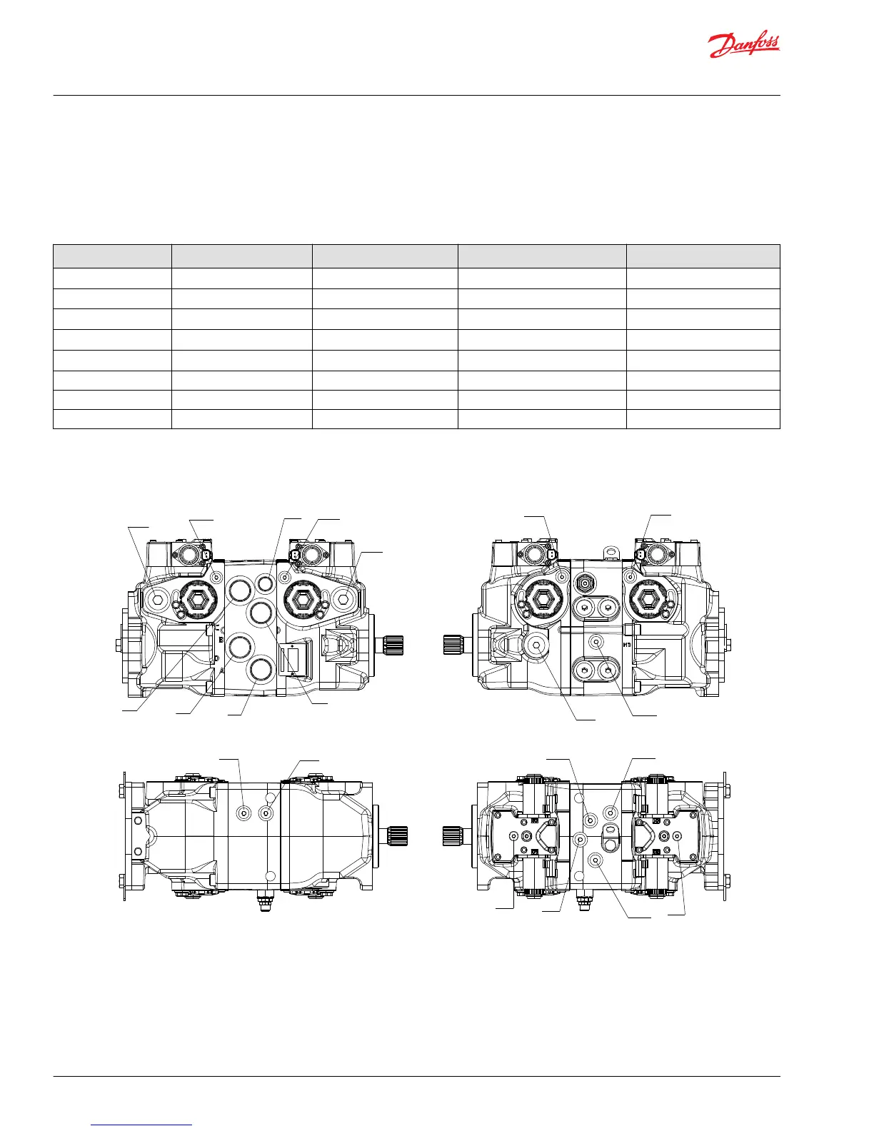
Port locations and gauge installation - 045/053
The following table and drawings show the port locations and gauge sizes needed. When testing system
pressures, calibrate pressure gauges frequently to ensure accuracy. Use snubbers to protect gauges.
Port information
Port identifier Port size Wrench size Reading Gauge size, bar [psi]
L1, L2, L3 1 1/16-12 UNF 2B 9/16 internal hex Case drain 10 bar [100 psi]
MA, MB, MC, MD 9/16-18 UNF 1/4 internal hex System pressure 600 bar [10,000 psi]
M3 9/16-18 UNF 2B 1/4 internal hex Charge pressure 50 bar [1000 psi]
M4, M5 7/16-20 UNF 2B 3/16 internal hex Servo pressure 50 bar [1000 psi]
AM3 9/16-18 UNF 2B 1/4 internal hex Alternate Charge pressure 50 bar [1000 psi]
A, B, C, D 1 5/16-12 - System ports -
E 7/8-14 - Charge filtration -
M14 7/16-20 1/4 internal hex Case gauge port 10 bar [100 psi]
Port locations
Service Manual
H1 45/53/60/68 Tandem Closed Circuit Axial Piston Pumps
Pressure measurements
26 |
©
Danfoss | June 2018 520L0928 | AX00000103en-US0303