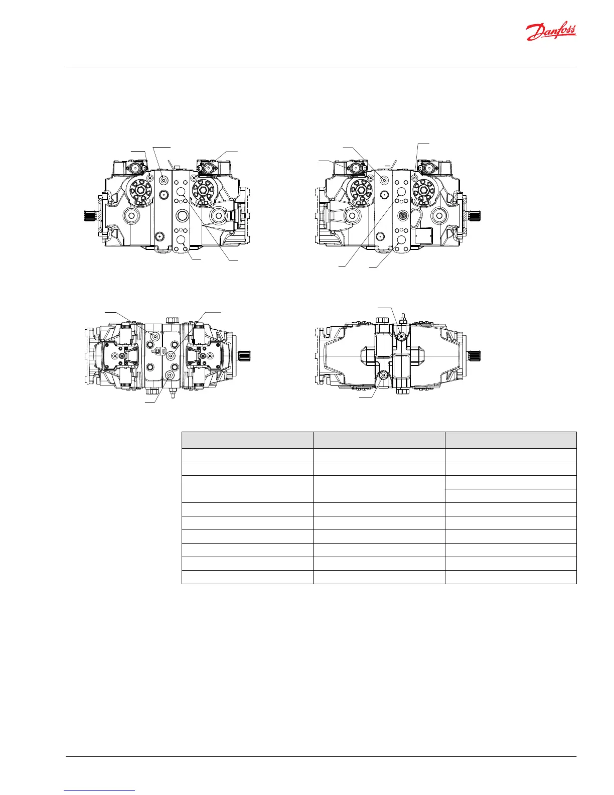
Item
Description
Port
1 Servo Cylinder -
M3, AM3 Charge port ISO 11926-1 9/16-18
A, B, C, D System port ISO 11926-1 1-5/16-12 (045/053)
Split flange M12 x 1.5 (060/068)
X7 (045/053) Brake gauge port ISO 11926-1 9/16-18
X7 (060/068) Brake gauge port ISO 11926-1 3/4-16
MA, MB, MC, MD System gauge port ISO 11926-1 9/16-18
M4, M5 Servo gauge port ISO 11926-1 7/16-20
E300 Servo cylinder clamp -
E350 Servo cylinder clamp bolt -
1. Run prime mover at 1800 min¯¹(rpm).
2. If using a PWM signal, ensure the signal is off. Check the servo pressure gauges. Ensure the differential
between M4 and M5 is less than 2.5 bar [36 psi].
3. Using a 3/4 in deep socket, unthread both servo cylinders 2-3 turns. This step ensures the servo
cylinders have no contact with the servo piston.
4. Stroke the pump by turning the control eccentric screw (or supplying current to solenoid C1) until the
servo pressure at port M4 is 1 to 2 bar [14– 29 psi] greater than at port M5 and the system pressure
gauges indicate displacement. Pressure should be greater at port MA for clockwise rotation, or MB for
counterclockwise rotation. This also indicates the servo piston is in contact with the servo cylinder on
side M5.
Service Manual
H1 45/53/60/68 Tandem Closed Circuit Axial Piston Pumps
Adjustments
©
Danfoss | June 2018 520L0928 | AX00000103en-US0303 | 45