7
VIIOS202 © Danfoss 07/2017
Installation Guide Danfoss Link™ DBR Installation Guide Danfoss Link™ DBR
Mounting
The Danfoss Link™ DBR is not recommended in application
without bypass valve. Install Danfoss Link™ DBR together with
e.g. AVDO bypass valve.
If boiler has internal bypass valve and installed with weather
compensation, the Danfoss Link™ DBR can be installed without
the Return Sensor, in operation mode “On when Heat Demand”
UK
NL
FR
UK
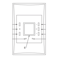
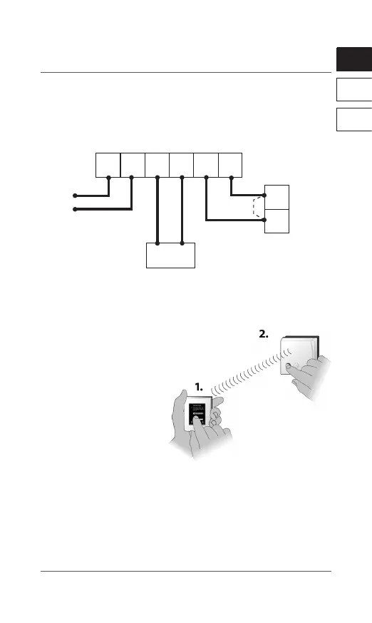
Wiring
1NL 234
230 V AC
ESM-11
T
T
Danfoss Link™
DBR
Electronics
Remove
jumper
if tted
Boiler ON/OFF
terminals
Note: Refer to boiler manufacturer’s manual for wiring connections
to the boiler.
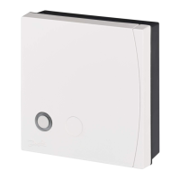
The process of adding the Danfoss Link™ DBR
to a system is performed on the Danfoss
Link™ CC.
Note that the Danfoss Link™ DBR
must be added as a Service
Device.
When adding, press and
release the install button,
and observe that the LED
gives a fast green ash.
If adding is successful the LED turns green permanently.
For further information, see the Danfoss Link™ CC instruction
manual.
Note: If adding the Danfoss Link™ DBR to the Danfoss Link™ CC is
unsuccessful, make sure the right Danfoss Link™ CC software
version is applied. Correct version: 4.1.0 or higher.
Adding the device