Application guidelines
13FRCC.PC.002.A4.22
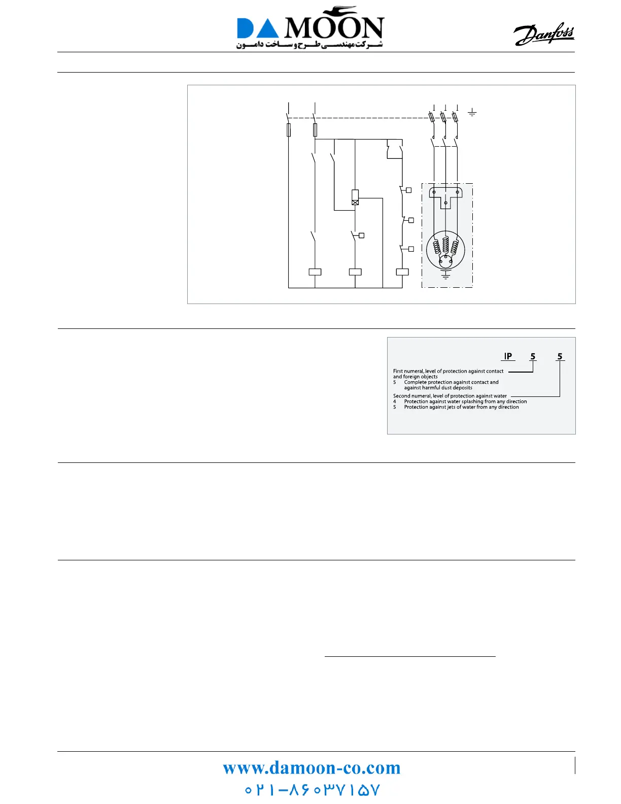
Electrical connections and wiring
Wiring diagram without
pump-down cycle
Control device TH
Optional short cycle timer (3 min) 180 s
Control relay KA
Compressor contactor KM
Safety lock out relay KS
H.P. switch HP
Fused disconnect Q1
Fuses F1
Compressor motor M
Discharge gas thermostat DGT
IP rating The compressor terminal boxes IP rating accord-
ing to CEI 529 are:
IP55 for NTZ048 - 136
IP54 for NTZ215 - 271.
The IP ratings are only valid when correctly sized
cable glands of the same IP rating are applied.
Internal motor protection
Voltage unbalance
Motor protection
Three phase compressors are internally protected
by a temperature / current-sensing bimetallic
protector, connected to the neutral point of the
star-connected stator windings. This internal
overload line break protects the motor against
overheating, current overload and locked rotor
conditions. If the motor were to be overloaded
and the protector trips, all 3-phases are cut out.
It might take up to several hours to reset and
restart the compressor.
Operating voltage limits are shown in section
"Voltage application range". The voltage applied
to motor terminals must lie within these limits
during both start-up and normal operation. The
maximum allowable voltage unbalance is 2%.
Voltage unbalance causes high amperage on one
or more phases, which in turn leads to overheat-
ing and possible motor damage.
The voltage unbalance is given by the following
formula:
Vavg = Mean voltage of phases 1, 2 and 3
V1-2 = Voltage between phases 1 and 2
V1-3 = Voltage between phases 1 and 3
V2-3 = Voltage between phases 2 and 3.
|Vavg - V1-2 |+|Vavg - V1-3 |+|Vavg - V2-3 |
2 xV
avg
% voltage unbalance: x 100
KM
L1 L3 L2
Q1
CONTROL CIRCUIT
F1F1
KM KA
KA KS
KS
KS
LP
HP
DGT
TH
180 s
85 52 019 - A
T1
T2
M
T3
KA KA
A1
A2
A3
 Loading...