Application guidelines
22 FRCC.PC.002.A4.22
Installation and service
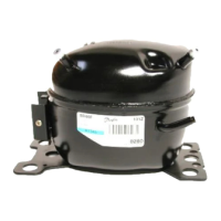
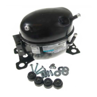
Compressor mounting
Compressor handling
Compressor handling,
mounting and connection
System cleanliness
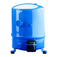
The compressor must be mounted onto a
horizontal surface with a maximum slope of
3 degrees. Always use the rubber mounting
grommets that are shipped with the compressor.
Mounting torques are listed in the below table.
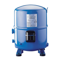
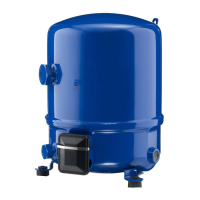
Maneurop® NTZ compressors must be handled
with care and all handling procedures must be
performed smoothly and gently. Each NTZ has
been tted with one lift ring which shall always
be used to lift the compressor. Once the com-
pressor is installed, the lift ring shall never be
used to lift the complete installation.
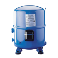
Always use the proper tools for transporting the
compressor. Keep the compressor in an upright
position during all handling tasks (manipulating,
transport, storage). The angle o the vertical
must not exceed 15 degrees.
System contamination is one of the main factors
that aects equipment reliability and compressor
service life. Therefore it is important to take care
of the system cleanliness when assembling a
refrigeration system. During the manufacturing
process, circuit contamination can be caused by:
• Brazing and welding oxides,
• Filings and particles from removing burrs from
pipe-work,
• Brazing ux,
• Moisture and air.
Only use clean and dehydrated, refrigera-
tion-grade copper tubes and silver alloy brazing
material. Clean all parts before brazing and
always purge nitrogen or CO
2
through the pipes
during brazing to prevent oxidation. If ux is
used, take every precaution to prevent the leak-
age of ux into the piping. The use of ux core
or ux coated braze wire or rod instead of brush
applied paste ux is strongly recommended. Do
not drill holes (e.g. for schrader valves) in parts of
the installation that are already completed, when
lings and burrs cannot be removed. Carefully
follow the instructions below regarding brazing,
mounting, leak detection, pressure test and mois-
ture removal. All installation and service work
shall only be done by qualied personnel re-
specting all procedures and using tools (charging
systems, tubes, vacuum pumps, etc.) dedicated
for R404A and R507.
Component
Torque (in.lb)
Min. Max.
Rotolock suction valve, NTZ048 - NTZ068 710 885
Rotolock suction valve, NTZ096 - NTZ271 885 1060
Rotolock discharge valve, NTZ048 – NTZ068 620 795
Rotolock discharge valve, NTZ096 - NTZ271 710 885
Electrical T-block screws HN°10-32 UNF x 9.5 - 27
Earth screw - 27
Oil sight glass (with black chloroprene gasket) 355 400
3/8” are oil equalisation nut 400 440
Schrader nut 100 150
Schrader valve (internal) 3.5 7
Mounting grommet bolt, NTZ048 – NTZ136 105 160
Mounting grommet bolt, NTZ215 - NTZ271 355 530
Belt crankcase heater - 35
 Loading...