11
50 Hz PSC/CSR* CSR only
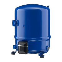
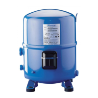
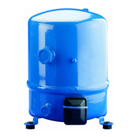
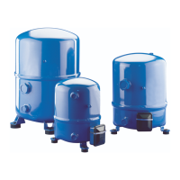
Models
Run
capacitors
(1)
Start
capacitors (2)
Start
relay
(A) μF (C) μF (B) μF
NTZ048 20 10 100
3ARR3J4A4
NTZ068 20 10 100
60 Hz PSC/CSR* CSR only
Models
Run
capacitors
(1)
Start
capacitors (2)
Start
relay
(A) μF (C) μF (B) μF
NTZ048 15 10 100
3ARR3J4A4
NTZ068 25 25 135
NTZ096 30 15 135
NTZ108 30 15 135
NTZ136 30 15 135
ELECTRICAL CONNECTIONS AND WIRING
Nominal capacitor values
and relays
* PSC: Permanent Split Capacitor
CSR: Capacitor Start Run
(1) Run capacitors: 440 volts
(2) Start capacitors: 330 Volts
Single phase motor
protection and suggested
wiring diagram
Single phase compressor motors are
internally protected by a temperature
/ current-sensing bimetallic protector
which senses the main and start wind-
ing current as well as motor winding
temperature. If the motor were to be
overloaded and the protector trips, it
might take up to several hours to reset
and restart the compressor.
The standard CSR wiring system pro-
vides additional motor torque at start-
up, by the use of a start capacitor in
combination with a run capacitor. The
start capacitor is only connected dur-
ing the starting operation and a poten-
tial relay disconnects it after the start
sequence. This sytem can be used for
refrigerant circuits with capillary tubes
or expansion valves.
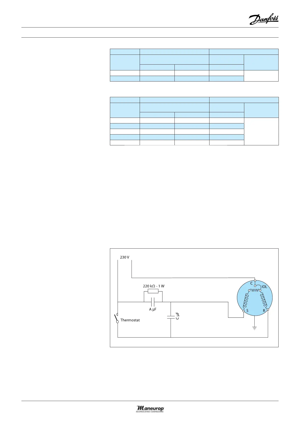
Single phase
PSC wiring
with trickle circuit
IOL Motor protector
A & C Run capacitors
C Common
S Start winding (auxiliary)
R Run winding (main)
 Loading...