2
ELECTRICAL
FULL STROKE CURRENT
85 ± 11.3 mA (single coil)
42 ± 5.6 mA (series coils)
85 ± 11.3 mA (parallel coils)
See Current vs. Swashplate Angle curve
NOMINAL INPUT IMPEDANCE
24.7 ohms, .093 henries, each coil
DEADBAND
32 ± 7 psi divided by the scale factor
HYDRAULIC
FILTRATION
The system hydraulics must have 10 micron or better
filtration. The pump will contain screen filters near the
interface to the EDC at the charge port and control port
locations. The pilot will have screen filters at its input and
output control ports.
FLUID
Automatic transmission fluid or hydraulic oil, such as
Mobil DTE 24 or equivalent
OIL VISCOSITY
40-6000 SSU
OIL TEMPERATURE
-40° C (-40° F) minimum; 104° C (220° F) maximum
OPERATING SUPPLY PRESSURE
Typically 300-400 psi above case pressure
RATINGS
SCALE FACTOR
1.15 psi/mA (single coil)
2.3 psi/mA (coils in series)
1.15 psi/mA (coils in parallel)
TEMPERATURE
The valve will meet all specifications over the range of
21° to 82° C (70° to 180° F)
TECHNICAL DATA
ELECTRICAL CHARACTERISTICS
(+) Voltage to Terminal
One of Dual Coils Dual Coils in Parallel Dual Coils in Series
Input Produces
Shaft Flow Out
Rotation Of Port
Clockwise A or C B or D A or C B or D A D A B
Counterclockwise A or C B or D A or C B or D A D B A
Start Current 14 mA with 0.43 Vdc 14 mA with 0.22 Vdc 7 mA with 0.43 Vdc
Full Stroke Current 85 mA with 2.3 Vdc 85 mA with 1.15 Vdc 42 mA with 2.3 Vdc
ABCD
++
+
BC D
A
+
BC D
A
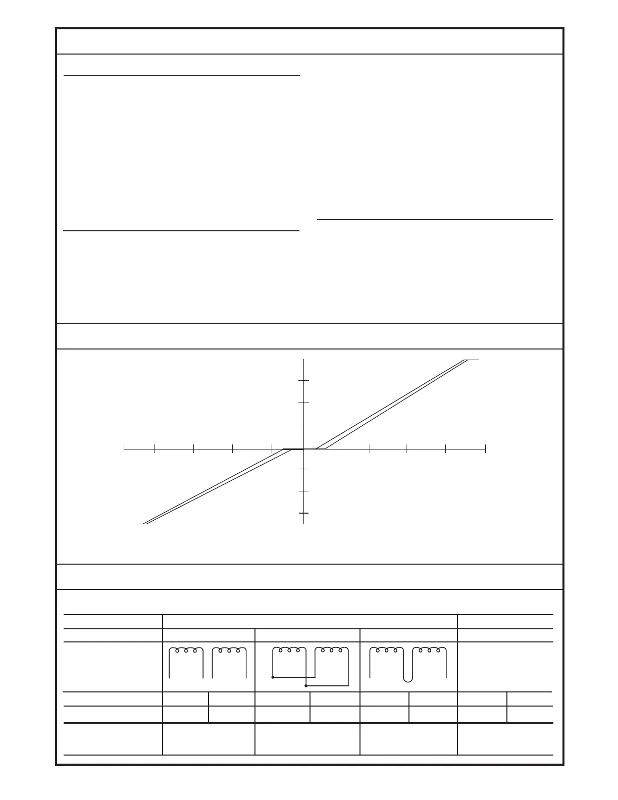
CURRENT VS. SWASHPLATE ANGLE
Current Vs. Swashplate Angle of the Single Coil MCV111B.
1390
15°
10°
5°
100
mA
80 60 40 20
20 40 60 80 100
mA
15°
10°
5°
INPUT SHAFT ROTATION VS. TERMINAL CONNECTION VS. OUTPUT FLOW
BLN-95-8995-4