EasyManua.ls Logo

Danfoss MMIGRS2 User Manual

Danfoss MMIGRS2
16 pages
To Next Page IconTo Next Page
Page #1 background imageLoading...
Page #1 background image
Principle
Instructions
AK-PC 572
Identification
Power supply
AK-PC 572
080G0320
24 V a.c. / d.c. 17 VA
EXD 316
084B8042
24 V a.c. / d.c. 10 VA
1.5 m: 080G0075
3.0 m: 080G0076
MMIGRS2
080G0294
RI8SR1ML 2019-01
IP 20
-20 - 60°C
(0 - 140°F)
RH max. 90% non condensing
AK-PC 572 17 VA
EXD 316, HP 10 VA
EXD 316, rec 10 VA
Stepper valve, HP _ _VA
Stepper valve rec. _ _VA

Other manuals for Danfoss MMIGRS2

Question and Answer IconNeed help?

Do you have a question about the Danfoss MMIGRS2 and is the answer not in the manual?

Danfoss MMIGRS2 Specifications

General IconGeneral
BrandDanfoss
ModelMMIGRS2
CategoryController
LanguageEnglish

Summary

Identification of System Modules

AK-PC 572 Controller

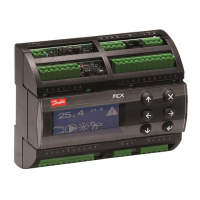
Main controller unit with 24 V a.c./d.c. 17 VA power supply.

EXD 316 Expansion Module

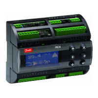
Expansion module with 24 V a.c./d.c. 10 VA power supply.

MMIGRS2 Communication Module

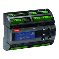
Communication module for system integration.

Power Supply Specifications

Component Power Consumption

Details power consumption for AK-PC 572, EXD 316, and stepper valves.

System Principle Diagram

Main Module Configuration

Analog Outputs (AO)

Configuration for analog outputs AO1, AO3, AO4 for frequency converters or EC motors.

Analog Inputs (AI)

Details for analog inputs AI1-AI4 for pressure transmitters.

Digital Inputs (DI)

Configuration for digital switch inputs DI1-DI8, used for shut-down or interruption.

Digital Outputs (DO)

Setup for digital outputs DO1-DO8, including solid state relays.

Communication Interfaces

Setup for CAN bus and Modbus communication.

High Pressure Module (Address 96)

Power and Battery

Power supply connection and battery backup for the HP module.

Stepper Valve Control

Configuration details for the FX ventil type CCMT stepper valve.

Sensor and Auxiliary Inputs/Outputs

Setup for sensor inputs, contact input AUX 2, and relay output AUX 2.

Receiver Module (Address 97)

Power and Battery

Power supply connection and battery backup for the receiver module.

Stepper Valve Control

Configuration details for the FX valve type CCMT stepper valve.

Auxiliary Inputs/Outputs

Setup for contact input AUX 3 and relay output AUX 3.

Addressing and Installation Notes

External Display Connection

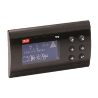
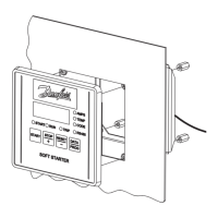
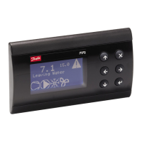
Wiring diagram and termination for external display.

Bitzer CRII Control

Using the pulse signal to control Bitzer CRII unloaders.

Module Addressing Procedure

Step-by-step guide to set module addresses (96 and 97).

Resetting Module Addresses

Procedure to reset incorrect module network IDs.

Related product manuals