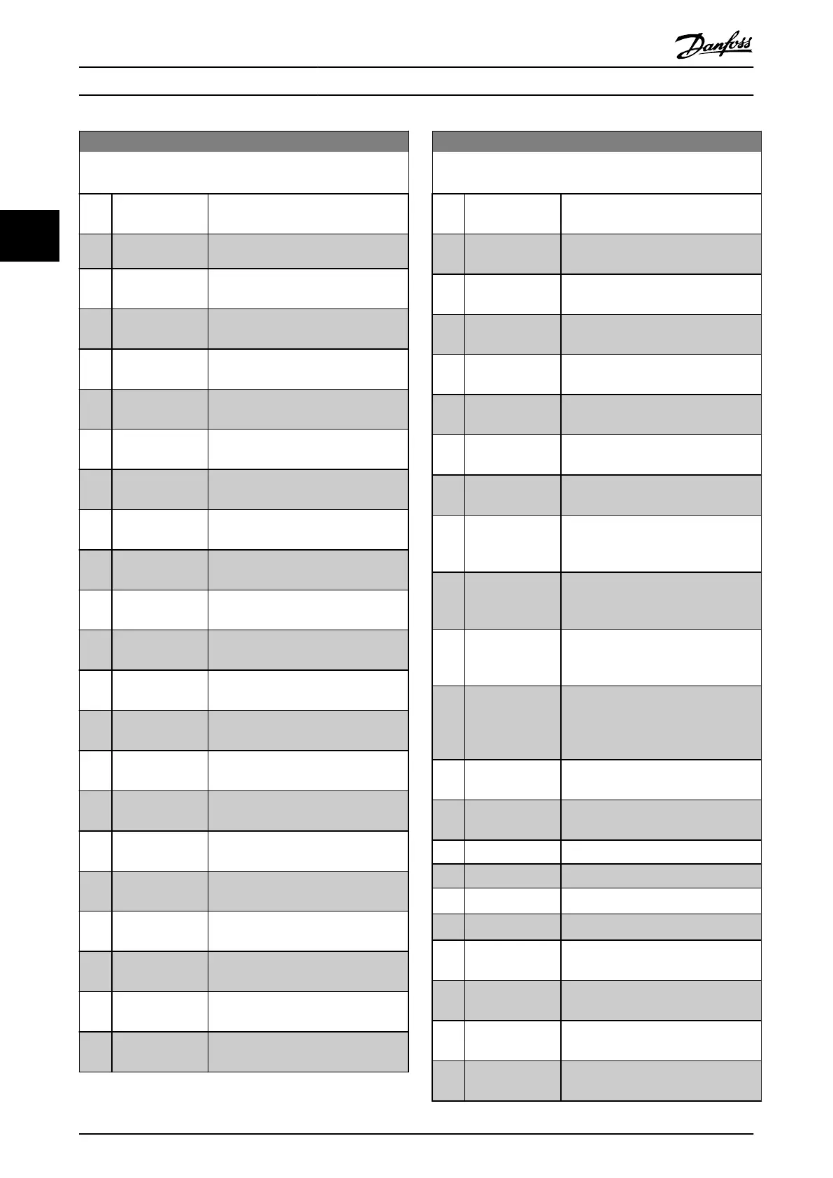
13-40 Logic Rule Boolean 1
Array [6]
Option: Function:
[9] Above I high
See chapter 3.7.3 5-3* Digital Outputs
for further description.
[10] Out of speed
range
[11] Below speed low
See chapter 3.7.3 5-3* Digital Outputs
for further description.
[12] Above speed
high
See chapter 3.7.3 5-3* Digital Outputs
for further description.
[13] Out of feedb.
range
See chapter 3.7.3 5-3* Digital Outputs
for further description.
[14] Below feedb. low
See chapter 3.7.3 5-3* Digital Outputs
for further description.
[15] Above feedb.
high
See chapter 3.7.3 5-3* Digital Outputs
for further description.
[16] Thermal warning
See chapter 3.7.3 5-3* Digital Outputs
for further description.
[17] Mains out of
range
See chapter 3.7.3 5-3* Digital Outputs
for further description.
[18] Reversing
See chapter 3.7.3 5-3* Digital Outputs
for further description.
[19] Warning
See chapter 3.7.3 5-3* Digital Outputs
for further description.
[20] Alarm (trip)
See chapter 3.7.3 5-3* Digital Outputs
for further description.
[21] Alarm (trip lock)
See chapter 3.7.3 5-3* Digital Outputs
for further description.
[22] Comparator 0 Use the result of comparator 0 in the
logic rule.
[23] Comparator 1 Use the result of comparator 1 in the
logic rule.
[24] Comparator 2 Use the result of comparator 2 in the
logic rule.
[25] Comparator 3 Use the result of comparator 3 in the
logic rule.
[26] Logic rule 0 Use the result of logic rule 0 in the
logic rule.
[27] Logic rule 1 Use the result of logic rule 1 in the
logic rule.
[28] Logic rule 2 Use the result of logic rule 2 in the
logic rule.
[29] Logic rule 3 Use the result of logic rule 3 in the
logic rule.
[30] SL Time-out 0 Use the result of timer 0 in the logic
rule.
13-40 Logic Rule Boolean 1
Array [6]
Option: Function:
[31] SL Time-out 1 Use the result of timer 1 in the logic
rule.
[32] SL Time-out 2 Use the result of timer 2 in the logic
rule.
[33] Digital input DI18 Use the value of DI18 in the logic rule
(High=TRUE).
[34] Digital input DI19 Use the value of DI19 in the logic rule
(High=TRUE).
[35] Digital input DI27 Use the value of DI27 in the logic rule
(High=TRUE).
[36] Digital input DI29 Use the value of DI29 in the logic rule
(High=TRUE).
[37] Digital input DI32 Use the value of DI32 in the logic rule
(High=TRUE).
[38] Digital input DI33 Use the value of DI33 in the logic rule
(High=TRUE).
[39] Start command This logic rule is TRUE if the frequency
converter is started either via digital
input, eldbus, or other.
[40] Drive stopped This logic rule is TRUE if the frequency
converter is stopped or coasted either
via digital input, eldbus, or other.
[41] Reset Trip This logic rule is TRUE if the frequency
converter is tripped (but not trip-
locked) and [Reset] is pressed.
[42] Auto Reset Trip This logic rule is TRUE if the frequency
converter is tripped (but not trip-
locked) and an automatic reset is
issued.
[43] OK Key This logic rule is TRUE if [OK] is
pressed.
[44] Reset Key This logic rule is TRUE if [Reset] is
pressed.
[45] Left Key
This logic rule is TRUE if [◄] is pressed.
[46] Right Key
This logic rule is TRUE if [►] is pressed.
[47] Up Key
This logic rule is TRUE if [
▲
] is pressed.
[48] Down Key
This logic rule is TRUE if [
▼
] is pressed.
[50] Comparator 4 Use the result of comparator 4 in the
logic rule.
[51] Comparator 5 Use the result of comparator 5 in the
logic rule.
[60] Logic rule 4 Use the result of logic rule 4 in the
logic rule.
[61] Logic rule 5 Use the result of logic rule 5 in the
logic rule.
Parameter Descriptions
VLT
®
HVAC Drive FC 102
112 Danfoss A/S © 03/2015 All rights reserved. MG11CE02
33
 Loading...


