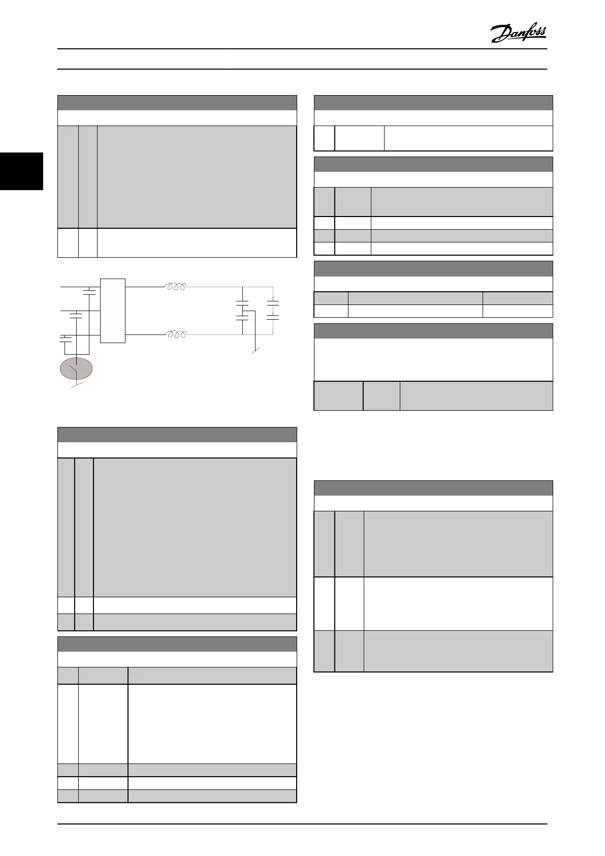
14-50 RFI Filter
Option: Function:
[0] O
Select [0] O if the frequency converter is fed by an
isolated mains source (IT mains).
If a lter is used, select [0] O during charging to
prevent a high leakage current making the RCD
switch.
In this mode, the internal RFI lter capacitors between
chassis and the mains RFI lter circuit are cut-out to
reduce the ground capacity currents.
[1] * On
Select [1] On to ensure that the frequency converter
complies with EMC standards.
Illustration 3.42 RFI Filter
14-51 DC Link Compensation
Option: Function:
The rectied AC-DC voltage in the frequency converter's
DC link is associated with voltage ripples. These ripples
can increase in magnitude with increased load. These
ripples are undesirable because they can generate
current and torque ripples. A compensation method is
used to reduce these voltage ripples in the DC link. In
general, DC Link Compensation is recommended for
most applications, but pay attention when operating in
eld weakening as it can generate speed oscillations at
the motor shaft. In eld weakening, it is recommended
to turn o DC-link compensation.
[0] O Disables DC-link compensation.
[1] On Enables DC-link compensation.
14-52 Fan Control
Option: Function:
Select the minimum speed of the main fan.
[0] * Auto
Select [0] Auto to run the fan only when the
internal temperature of the frequency
converter is in the range +35 °C to approxi-
mately +55 °C. The fan runs at low speed at
+35 °C and at full speed at approximately
+55 °C.
[1] On 50%
[2] On 75%
[3] On 100%
14-52 Fan Control
Option: Function:
[4] Auto (Low
temp env.)
14-53 Fan Monitor
Option: Function:
Select the frequency converter action if a fan
fault is detected.
[0] Disabled
[1] * Warning
[2] Trip
14-55 Output Filter
Option: Function:
[0] * No Filter
[2] Sine Wave Filter Fixed
14-59 Actual Number of Inverter Units
This parameter is only relevant for high power frequency
converters.
Range: Function:
Size related* [ 1 - 1 ] Sets the actual number of operating
inverter units.
3.14.7 14-6* Auto Derate
This group contains parameters for derating the frequency
converter in case of high temperature.
14-60 Function at Over Temperature
Option: Function:
If either heatsink or control card temperature
exceeds a factory-programmed temperature limit, a
warning is activated. If the temperature increases
further, select whether the frequency converter
should trip (trip lock) or derate the output current.
[0] * Trip The frequency converter trips (trip lock) and
generate an alarm. Cycle Power to reset the alarm.
The motor restarts when the heat sink temperature
has dropped below the alarm limit.
[1] Derate If the critical temperature is exceeded, the output
current is reduced until the allowable temperature
has been reached.
3.14.8 No Trip at Inverter Overload
In some pump systems, the frequency converter has not
been sized properly to yield the current needed in all
points of the operational ow-head characteristic. At these
points, the pump needs a current higher than the rated
current of the frequency converter. The frequency
converter can yield 110% of the rated current continuously
Parameter Descriptions
VLT
®
HVAC Drive FC 102
122 Danfoss A/S © 03/2015 All rights reserved. MG11CE02
33
 Loading...


