23-63 Timed Period Start
Range: Function:
Size
related*
[ 0 -
0 ]
NOTICE
The frequency converter has no back-up
of the clock function and the set date/
time is reset to default (2000-01-01
00:00) after a power-down unless a real
time clock-module with back-up is
installed. Consequently, the logging is
stopped until date/time is readjusted in
parameter 0-70 Date and Time. In
parameter 0-79 Clock Fault it is possible
to programme a warning if in case the
clock has not been set properly, for
example after a power-down.
NOTICE
When mounting an analog I/O MCB 109
option card, a battery back-up of the
date and time is included.
Set the date and time at which the trending
starts the update of the timed bin counters.
Date format depends on setting in
parameter 0-71 Date Format, and time format
on setting in parameter 0-72 Time Format.
23-64 Timed Period Stop
Range: Function:
Size
related*
[ 0 -
0 ]
NOTICE
When mounting an analog I/O MCB
109 option card, a battery back-up of
the date and time is included.
Set the date and time at which the trend
analyses must stop updating the timed bin
counters.
23-64 Timed Period Stop
Range: Function:
Date format depends on setting in
parameter 0-71 Date Format, and time format
on setting in parameter 0-72 Time Format.
23-65 Minimum Bin Value
Range: Function:
Size
related*
[ 0 -
100
%]
Array with 10 elements ([0]-[9] below
parameter number in display). Press [OK] and
step between elements with [
▲
] and [
▼
].
Set the minimum limit for each interval in
parameter 23-61 Continuous Bin Data and
parameter 23-62 Timed Bin Data. Example: If
selecting [1] counter and changing setting from
10% to 12%, [0] counter is based on the
interval 0–<12% and [1] counter on interval
12%–<20%.
23-66 Reset Continuous Bin Data
Option: Function:
[0] * Do not
reset
Select [1] Do reset to reset all values in
parameter 23-61 Continuous Bin Data. After
pressing [OK], the setting of the parameter
value automatically changes to [0] Do not reset.
[1] Do reset
23-67 Reset Timed Bin Data
Option: Function:
Select [1] Do reset to reset all counters in
parameter 23-62 Timed Bin Data.
After pressing [OK], the setting of the
parameter value automatically changes to [0]
Do not reset.
[0] * Do not
reset
[1] Do reset
3.21.5 23-8* Payback Counter
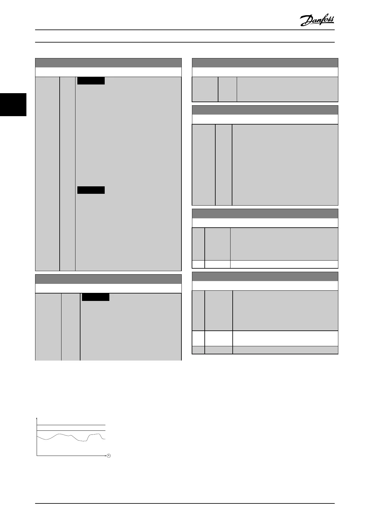
The frequency converter includes a feature which can give a rough calculation on payback in cases where the frequency
converter has been installed in an existing plant to ensure energy savings. Reference for the savings is a set value to
represent the average power yielded before the upgrade with variable speed control.
130BA259.11
P
Actual power yielded
with variable
speed control
(read P 16-10/11)
Reference power
(at xed speed)
(P 23-80)
Rated power for the
motor size used
(P 1-20/21)
Illustration 3.65 Variable Speed Control
Parameter Descriptions
VLT
®
HVAC Drive FC 102
182 Danfoss A/S © 03/2015 All rights reserved. MG11CE02
33
 Loading...


