VLT
®
5000/6000/8000 Series
Introduction
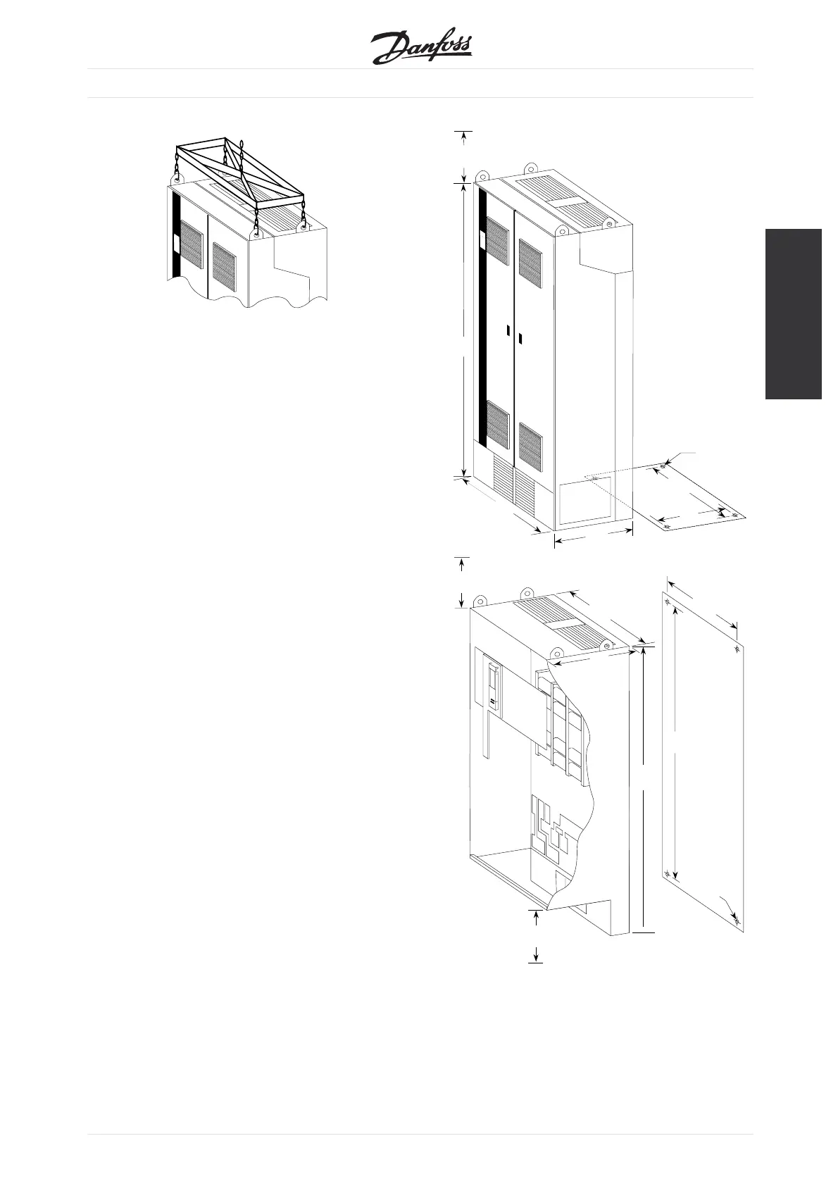
•
Remove the metal locking tabs and the
remaining crate panels.
•
On IP 00 versions remove the clear plastic safety
barr
ier from the front of the unit to prevent
the possibility of breaking during positioning
of the VLT frequency converter.
•
The VLT frequency converter is now ready to
be lifted and positioned in the installation site.
NOTE: On IP 00 versions there are inductors
bolted to the bottom of the crate. Lift the
VLT frequency converter high enough to allow
clearance over these inductors.
•
Obs
erve cooling and ventilation requirements given
in the "Installation Site" section of this manual.
•
Secure to the floor using the four holes provided
in the bottom of the unit. On IP 00 versions
secure to the panel using the four mounting holes
provided in the back. Refer to the dimensional
drawings in this instruction manual.
79.1
(2010)
42.3
(1075)
47.2
(1200)
23.6
(600)
18.7
(475)
4 x ø0.63
(16)
Mounting holes in
bottom panel
Min. free air space
above the drive
15.7
(400)
72.7
(1847)
41.9
(1065)
19.3
(490)
43.3
(1099)
74.6
(1896)
4 x ø0.63
(16)
Mounting holes
in back panel
15.7
(400)
Min. free air space
below the drive
15.7
(400)
Min. free air space
above the drive
MG.56.A2.02 - VLT is a registered Danfoss trademark
5
 Loading...


