CAUTION
A door fan(s) is required on the enclosure to remove the
heat losses not contained in the backchannel of the
frequency converter and any additional losses generated
from other components installed inside the enclosure.
The total required air flow must be calculated so that the
appropriate fans can be selected. Some enclosure
manufacturers offer software for performing the
calculations (i.e. Rittal Therm software). If the frequency
converter is the only heat generating component in the
enclosure, the minimum airflow required at an ambient
temperature of 45
o
C for the D3 and D4 frequency
converters is 391 m
3
/h (230 cfm). The minimum airflow
required at an ambient temperature of 45
o
C for the E2
frequency converter is 782 m
3
/h (460 cfm).
Airflow
The necessary airflow over the heat sink must be secured.
The flow rate is in Table 3.11.
Enclosure
protection Enclosure type
Door fan(s)/
Top fan
airflow
Heat sink
fan(s)
IP21/NEMA 1
IP54/NEMA 12
D1 and D2
170 m
3
/h
(100 cfm)
765 m
3
/h
(450 cfm)
E1 P315T5,
P450T7,
P500T7
340 m
3
/h
(200 cfm)
1105 m
3
/h
(650 cfm)
E1 P355-
P450T5, P560-
P630T7
340 m
3
/h
(200 cfm)
1445 m
3
/h
(850 cfm)
IP21/NEMA 1 F1, F2, F3 and
F4
700 m
3
/h
(412 cfm)*
985 m
3
/h
(580 cfm)*
IP54/NEMA 12 F1, F2, F3 and
F4
525 m
3
/h
(309 cfm)*
985 m
3
/h
(580 cfm)*
IP00/Chassis D3 and D4
255 m
3
/h
(150 cfm)
765 m
3
/h
(450 cfm)
E2 P315T5,
P450T7,
P500T7
255 m
3
/h
(150 cfm)
1105 m
3
/h
(650 cfm)
E2 P355-
P450T5, P560-
P630T7
255 m
3
/h
(150 cfm)
1445 m
3
/h
(850 cfm)
* Airflow per fan. enclosure type F contain multiple fans.
Table 3.11 Heat Sink Air Flow
NOTICE
The fan runs for the following reasons:
1. AMA
2. DC Hold
3. Pre-Mag
4. DC Brake
5. 60% of nominal current is exceeded
6. Specific heat sink temperature exceeded (power
size dependent)
7. Specific Power Card ambient temperature
exceeded (power size dependent)
8. Specific Control Card ambient temperature
exceeded
Once the fan is started it will run for minimum 10
minutes.
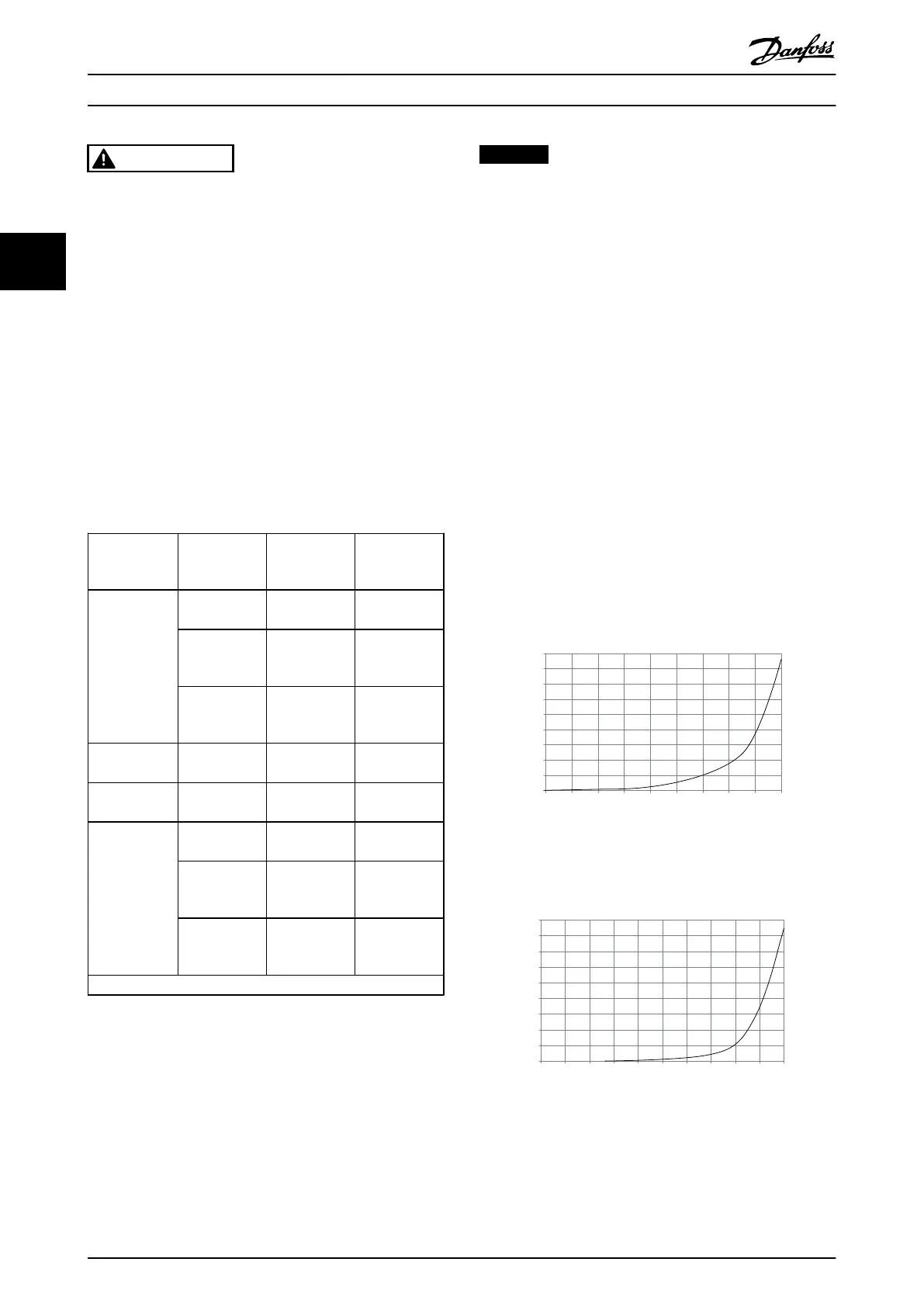
External ducts
If additional duct work is added externally to the Rittal
cabinet the pressure drop in the ducting must be
calculated. Use the charts below to derate the frequency
converter according to the pressure drop.
90
80
70
60
50
40
30
20
10
0
0 0.5 4.9 13 27.3 45.9 66 89.3 115.7 147
(%)
(Pa)
Pressure Increase
Drive Derating
130BB007.10
Illustration 3.36 D Enclosure Derating vs. Pressure Change
Frequency converter air flow: 450 cfm (765 m
3
/h)
90
80
70
60
50
40
30
20
10
0
(%)
Drive Derating
0 0 0.1 3.6 9.8 21.5 43.4 76 237.5 278.9
(Pa)
Pressure Change
130BB010.10
147.1
Illustration 3.37 E Enclosure Derating vs. Pressure Change
(Small Fan), P315T5 and P450T7-P500T7
Frequency converter air flow: 650 cfm (1105 m
3
/h)
How to Install VLT AQUA Drive FC 202 Operation Instructions
34 MG20P402 - Rev. 2013-12-16
33

 Loading...


