5.1.5 Q5 Changes Made
Q5 Changes Made can be used for fault finding.
Select Changes made to get information about:
•
the last 10 changes. Use the up/down navigation
keys to scroll between the last 10 changed
parameters.
•
the changes made since default setting.
Select Loggings to get information about the display line
read-outs. The information is shown as graphs.
Only display parameters selected in parameter 0-20 Display
Line 1.1 Small and 0-24 Display Line 3 Large can be viewed.
It is possible to store up to 120 samples in the memory for
later reference.
Note that the parameters listed in Table 5.6 to Table 5.6 for
Q5 only serve as examples as they vary depending on the
programming of the particular frequency converter.
Parameter 20-94 PID Integral Time
Parameter 20-93 PID Proportional Gain
Parameter 20-93 PID Proportional Gain
Parameter 20-94 PID Integral Time
Analog Input 53
Analog Input 54
5.1.6 Q6 Loggings
Q6 Loggings can be used for fault finding.
Notice that the parameters listed in Table 5.6 for Q6 only
serve as examples as they vary depending on the
programming of the particular frequency converter.
Reference
Analog Input 53
Motor Current
Frequency
Feedback
Energy Log
Trending Cont Bin
Trending Timed Bin
Trending Comparison
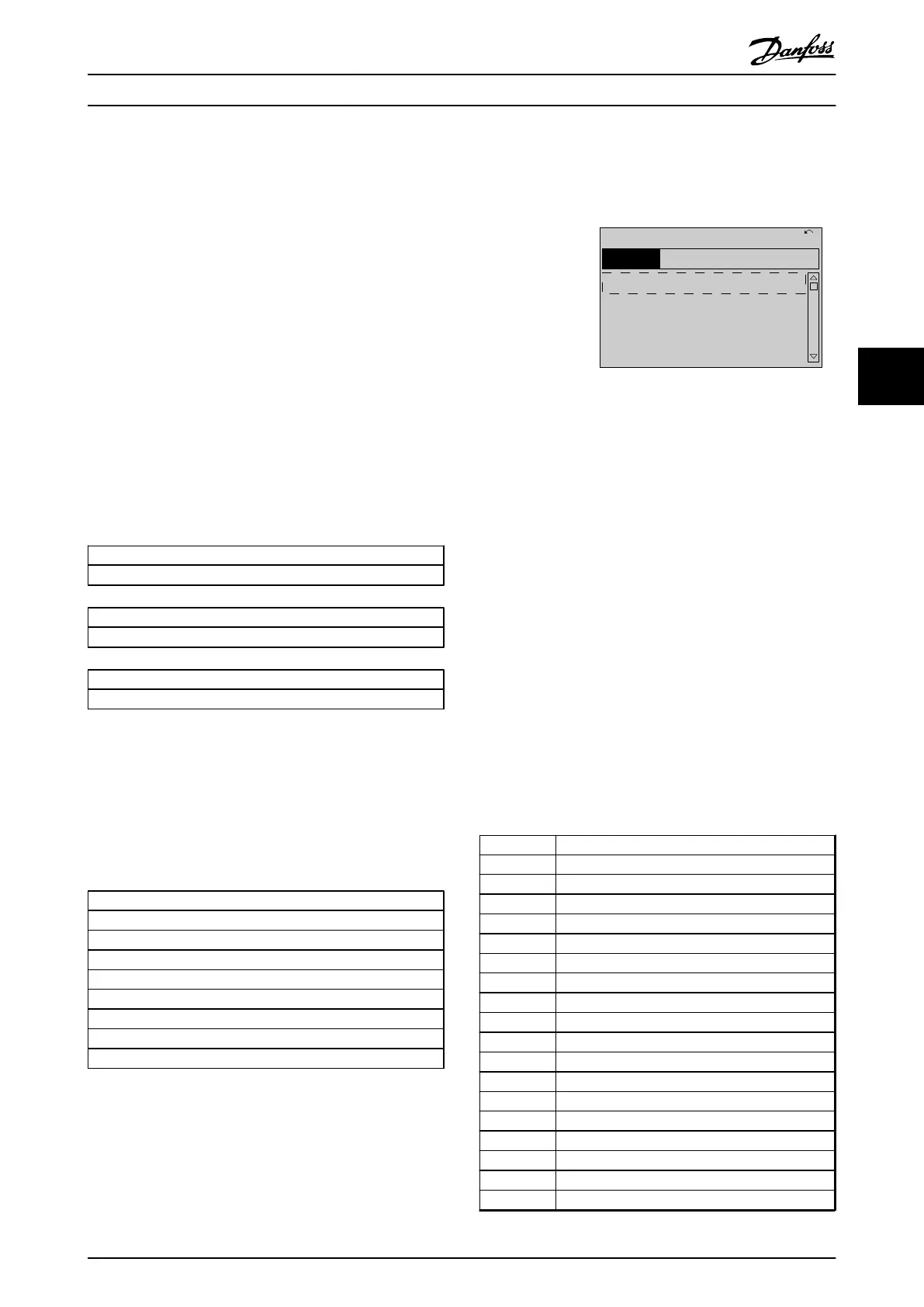
5.1.7 Main Menu Mode
Both the GLCP and NLCP provide access to the main menu
mode. Select the Main Menu mode by pressing the [Main
Menu] key. Illustration 5.9 shows the resulting read-out,
which appears on the display of the GLCP.
Lines 2 through 5 on the display show a list of parameter
groups which can be selected by toggling the up and
down keys.
130BP066.10
1107 RPM
0 -
**
Operation/Display
1 -
**
Load/Motor
2 -
**
Brakes
3 -
**
Reference / Ramps
3.84 A 1 (1)
Main menu
Illustration 5.9 Display Example
Each parameter has a name and number which remain the
same regardless of the programming mode. In the Main
Menu mode, the parameters are divided into groups. The
first digit of the parameter number (from the left) indicates
the parameter group number.
All parameters can be changed in the Main Menu. The
configuration of the unit (parameter 1-00 Configuration
Mode) determines other parameters available for
programming. For example, selecting closed loop enables
additional parameters related to closed loop operation.
Option cards added to the unit enable additional
parameters associated with the option device.
5.1.8
Parameter Selection
In the Main Menu mode, the parameters are divided into
groups. Select a parameter group by means of the
navigation keys.
The following parameter groups are accessible:
Group no.
Parameter group
0-** Operation/Display
1-** Load/Motor
2-** Brakes
3-** References/Ramps
4-** Limits/Warnings
5-** Digital In/Out
6-** Analog In/Out
8-** Comm. and Options
9-** Profibus
10-** CAN Fieldbus
11-** LonWorks
13-** Smart Logic
14-** Special Functions
15-** FC Information
16-** Data Readouts
18-** Data Readouts 2
20-** FC Closed Loop
21-** Ext. Closed Loop
How to programme the freque... VLT AQUA Drive FC 202 Operation Instructions
MG20P402 - Rev. 2013-12-16 83
5 5

 Loading...


